I finally got to smoke test the transmitter today. After some trial and error on the input matching for the driver stage I got around 25W out of the radio. I can't see any way to increase this without another stage so I am adding one more stage in the near future.
Harmonics will be a big issue. The second harmonic is around 10dB down, the third around 20dB down. While some improvement can be expected when the low pass filter is rebuilt, I don't expect it will be good enough in the current form. I know the harmonics are already present in the exciter output, so my plan is to put a band pass filter after the exciter and before the pre-driver that I will incorporate into the transmitter.
The good news is that the matching sections from the collector of the driver stage onwards all appeared close to correct. The output of the exciter did not appear to be a good match to 50ohms hence I had to re-jig the input matching to the driver on the run. Since I will have plenty of gain with another stage I will pad the output of the exciter with a 5dB or so attenuator to make it look like a better match to the filter I will build.
73's
Richard
Wednesday, 28 December 2016
Tuesday, 20 December 2016
Matching Resistors
I had a need for matched resistors in preparation for a coming project. I could have purchased some 0.1% tolerance parts, but since the value wasn't critical I thought I would have a go at matching by hand using a Wheatstone bridge. As it turned out I exceeded the 0.1% tolerance I could have purchased with ease.
Since I had no constraints on the resistance value I grabbed 25 or so 36k resistors. I don't know the tolerance specification of these but I expect they are 5% tolerance. Since I didn't think I would ever use these it didn't matter if I wasted them. I soldered three of them onto a piece of veroboard with connections for the power supply and meter. The fourth resistor would be manually placed across the tracks of the veroboard and held there with an eraser or other non-conductive stick.

The voltage difference represents how equal in ratio the resistor being tried is to those already in the circuit. It doesn't matter that none of the fixed resistors are matched. We are simply measuring the voltage difference for each resistor we trial. When the voltage difference is the same then the resistors we tried are the same.
In no time I had 2 pairs of resistors matched to within 1mV. I did the maths and that represents a 12 ohm difference, or 0.03% of 36k.
Who would have thought it could be that easy. Viva la Wheatsone Bridge.
Regards
Richard
Saturday, 17 December 2016
Unilab 10m FM conversion Transmitter PA mods - Final Stage revisited
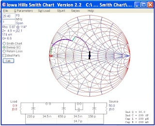
So I was sitting in front of the TV tonight and after a few comments about the show on TV I was banished to my shack. I started to read a few application notes on transistor matching and working the examples up in the smith chart to make sure I was getting the hang of how to use the Iowa Hills Smith Chart software. It dawned on me that I had not described how to determine if the matching network was suitable for the range of intended frequencies.
This is really easy and full credit to the author. Once we have our matching network at the design frequency we can select the option to "Sweep SC" on the right hand edge of the window and a black line shows how the load is transformed as the frequency is swept according the the span setting. I got the following:
 Which intuitively is better than a big black line but by how much? Click on the Return Loss button and you get:
 Which shows the return loss over the transmitting frequencies will be better than 20dB ie a good match
I can't wait to smoke test this!
73's
Richard
This is really easy and full credit to the author. Once we have our matching network at the design frequency we can select the option to "Sweep SC" on the right hand edge of the window and a black line shows how the load is transformed as the frequency is swept according the the span setting. I got the following:


I can't wait to smoke test this!
73's
Richard
Thursday, 15 December 2016
Unilab 10m FM conversion Transmitter PA mods - Driver Stage
I had a chance to rummage around in the junk box yesterday. If you're wondering why I would turn to a transistor I recover from a radio, instead of buying online, see my post at http://vk6tt.blogspot.com/2016/05/hf-transmitting-transistors-for-qrp.html
Anyway, the first radio touched was a Philips 828 E band. They contain a BLY87 which would be a good candidate as a driver. However, they are stud mounted so that could be awkward.
The next radio was a RT85 for low band. They use a Mitsubishi 2SC1971 as a driver which is a nominal 6W VHF high band transistor. Not quite the 10W I was looking for but it forced me to rethink my approach.
The MRF247 final transistor has a gain of 8.5db at 175MHz. Adjusting for frequency at 6dB per octave that equates to 23.8dB at 30MHz. Much more than the 10dB I was allowing for. The full gain at 30MHz cannot be used if oscillations are to be avoided. However, if I shoot for 13dB of gain then the 2SC1971 would only be required to produce 5W, well within it's rating.
Adjusting the quoted gain for frequency suggests the 2SC1971 has 25dB of gain at 30MHz. Again, way too high. But the prospect of avoiding a pre-driver stage is a tease since a gain of 13dB from the driver stage dictates an input power of 250mW to achieve 100W from the PA strip. The exciter delivers 100mW. Quite close and maybe the gain per stage I have allowed is too conservative.
I'm going to try just a driver stage and dispense with the pre-driver.

I had to revise the input stage to the PA transistor for the increased collector load the driver stage required. After several iterations with the smith chart I concluded the higher collector load required meant the existing matching configuration could not be made to work.
My approach now is:
73's
Richard
Anyway, the first radio touched was a Philips 828 E band. They contain a BLY87 which would be a good candidate as a driver. However, they are stud mounted so that could be awkward.
The next radio was a RT85 for low band. They use a Mitsubishi 2SC1971 as a driver which is a nominal 6W VHF high band transistor. Not quite the 10W I was looking for but it forced me to rethink my approach.
The MRF247 final transistor has a gain of 8.5db at 175MHz. Adjusting for frequency at 6dB per octave that equates to 23.8dB at 30MHz. Much more than the 10dB I was allowing for. The full gain at 30MHz cannot be used if oscillations are to be avoided. However, if I shoot for 13dB of gain then the 2SC1971 would only be required to produce 5W, well within it's rating.
Adjusting the quoted gain for frequency suggests the 2SC1971 has 25dB of gain at 30MHz. Again, way too high. But the prospect of avoiding a pre-driver stage is a tease since a gain of 13dB from the driver stage dictates an input power of 250mW to achieve 100W from the PA strip. The exciter delivers 100mW. Quite close and maybe the gain per stage I have allowed is too conservative.
I'm going to try just a driver stage and dispense with the pre-driver.
I had to revise the input stage to the PA transistor for the increased collector load the driver stage required. After several iterations with the smith chart I concluded the higher collector load required meant the existing matching configuration could not be made to work.
My approach now is:
- C1, currently 100pF, is padded with a 10nF capacitor,
- removed the 2 turn coil L1,
- pad the input of the strip-line with an extra 860pF of capacitance using two capacitors, 470pF and 390pF.
73's
Richard
Saturday, 10 December 2016
Unilab 10m FM conversion Transmitter PA mods - Final Stage
So, we now turn our attention to the final part of the modification. I suspect this will be the hardest part of the whole project. The existing PA needs a fair amount of work to get it running at 10m.
The challenges arises because:
If the MRF247 cannot be coaxed into service it will effectively mean a whole new PA strip. Perhaps Murphy is elsewhere today.
Since the MRF247 is specified as a 75W transistor I decided that would be the target output power. However, I'd design the matching for each stage for a 30% margin for the output power i.e. almost 100W. It may transpire that I have more gain than the 10dB per stage I am allowing for and since the MRF247 could be driven towards 100W I wasn't going to say no to the extra 25W if it eventuated. There is no data that I could find on the series equivalent impedances outside the specified range of 136MHz to 175MHz so I had to make some assumptions for the matching networks. I assumed the following:

In an attempt to understand how the Unilab designers got the MRF247 to work outside it's specified range I looked closely at the input networks. I knew the BGY32 was a 50ohm output device. And the MRF247 was likely to have a series input impedance of 0.57+j0.3 at 77MHz. To test this assumption I tried a few software packages until I found one that helped me understand this: Iowa Hills Smith Chart software.
I found this software intuitively easy to use. It wasn't the first Smith Chart software that I tried but like the filter software from Iowa Hills this is clearly written by someone who uses the software. I do recommend you try this software.
With the values shown on the circuit I was able to confirm a match was possible at 77MHz between 50ohmns and the PA transistors input impedance of 0.57+j0.3. This was true whether the stripline was modelled and an inductor or as a stripline. In the end I left is as an inductor:

The next step was to see what I would have to change to get this existing input matching section to match a source of 9.4ohms. This would be the collector load required for a driver to deliver almost 10W. For a class C amplifier this is derived from the formula Po = Vcc * Vcc / ( 2 * R ).
With just an extra capacitor and a different inductor we can achieve a good match. An additional 180p capacitor at the BGY32 end of the stripline and an inductor of 86nH replacing the coil that is there is all that might be required.
 So far, so good. I repeated the exercise for the output stage and decided that two 34.5nH coils and a 510pF capacitor to pad C603, or a 220p and 270p in parallel, would be a good starting point.

I'm going to make the changes outlined above and check my junk box for driver transistors before I progress any further.
73's
Richard
The challenges arises because:
- The BGY32 module is designed to work between 66MHz and 88MHz. This has to be replaced with a home brew alternative, and
- The MRF247 was never specified outside the 136-175MHz band, and
- I will try to use transistors that are readily available.
If the MRF247 cannot be coaxed into service it will effectively mean a whole new PA strip. Perhaps Murphy is elsewhere today.
Since the MRF247 is specified as a 75W transistor I decided that would be the target output power. However, I'd design the matching for each stage for a 30% margin for the output power i.e. almost 100W. It may transpire that I have more gain than the 10dB per stage I am allowing for and since the MRF247 could be driven towards 100W I wasn't going to say no to the extra 25W if it eventuated. There is no data that I could find on the series equivalent impedances outside the specified range of 136MHz to 175MHz so I had to make some assumptions for the matching networks. I assumed the following:
In an attempt to understand how the Unilab designers got the MRF247 to work outside it's specified range I looked closely at the input networks. I knew the BGY32 was a 50ohm output device. And the MRF247 was likely to have a series input impedance of 0.57+j0.3 at 77MHz. To test this assumption I tried a few software packages until I found one that helped me understand this: Iowa Hills Smith Chart software.
I found this software intuitively easy to use. It wasn't the first Smith Chart software that I tried but like the filter software from Iowa Hills this is clearly written by someone who uses the software. I do recommend you try this software.
With the values shown on the circuit I was able to confirm a match was possible at 77MHz between 50ohmns and the PA transistors input impedance of 0.57+j0.3. This was true whether the stripline was modelled and an inductor or as a stripline. In the end I left is as an inductor:

The next step was to see what I would have to change to get this existing input matching section to match a source of 9.4ohms. This would be the collector load required for a driver to deliver almost 10W. For a class C amplifier this is derived from the formula Po = Vcc * Vcc / ( 2 * R ).
With just an extra capacitor and a different inductor we can achieve a good match. An additional 180p capacitor at the BGY32 end of the stripline and an inductor of 86nH replacing the coil that is there is all that might be required.


I'm going to make the changes outlined above and check my junk box for driver transistors before I progress any further.
73's
Richard
Wednesday, 7 December 2016
Unliab 10M FM Conversion - Exciter Board
If you have been following along we pick up from the last instalment and detail what changes are needed once the transmit VCO board is working. The big issue with this project is the output spectrum. We have taken a 80MHz broadband design and pushed it down to 30MHz. As a result, the output spectrum resembles that of a tripler!
The problem stems from the amplifier stage immediately after the VCO board. This is the final stage in the exciter and it really works well as a tripler. And it is quite good as a doubler too! What I did was to alter the circuit back to a narrow band design with some selectivity.
I now have a 100mW exciter but I will have to consider the output spectrum more carefully as I progress to rebuild the PA.
73's
Richard
The problem stems from the amplifier stage immediately after the VCO board. This is the final stage in the exciter and it really works well as a tripler. And it is quite good as a doubler too! What I did was to alter the circuit back to a narrow band design with some selectivity.
- Pad C324, the 100pF input capacitor, with 1000pF
- Remove C328 and C329, the two 1000pF emitter bypass capacitors
- Remove L305, the tapped bifialar transformer wound on a ferrite bead.
- Remove the resistor that was in parallel with this. Mine was a 680ohm resistor.
- Clean out the holes and solder in 3 pins from a 0.1" header strip.
- Take a T50-2 toroid, wind 16turns with a tap at 4 turns. (I have plenty of these if you're stuck)
- Solder the toroid across the outside of the three pins. The cold end, that closest to the tap, goes to the pin towards the centre of the board.
- The tap goes to the middle of the three pins.
- Solder a trim cap, say 40pF, across the two outside pins of the header.
- Adjust FVR301 for maximum D voltage on TP303
- Tune the trim cap for strongest output on 10m.
I now have a 100mW exciter but I will have to consider the output spectrum more carefully as I progress to rebuild the PA.
73's
Richard
Sunday, 4 December 2016
Unilab 10m FM conversion - Transmitter VCO Board
The transmit VCO proved to be much more challenging. I started with calculated values for the capacitors and used the same biasing of the varactors as I discussed in the receiver VCO conversion.
This time I used a toroid in the tank circuit, a T50-2. I started with 12 turns but ended up removing 2 turns. I removed the resistor and thermistor and soldered a link on the source choke to ground. While I used a 91k resistor in the gate, 100k will be fine. The picture below still shows the varactor biasing diodes I put in place for testing. Remember to remove them before installation back in the radio!

Installing the VCO board back in the radio I found myself going in circles solving loop lock up followed by a poor output spectrum. Rather than bore you with the sorry tale let's cut to the chase!
The mmic buffer used is very susceptible to being over-driven and generating harmonics. Yet a small reduction in output means the pre-scaler does not get sufficient drive to work properly. I made the following changes:
If you haven't been able to find the circuit for this radio on the web here is a partial snapshot to help:

At this point I have a PLL which locks up and a nice waveform going into the remaining stages of the exciter.
Just like the receiver VCO board, I now looked at the variation in the control voltage as I locked at the top and bottom end of the 10m FM segment. The maths demonstrated that the existing loop filter was "awkward". I ended up putting a second varicap in parallel with the existing one and changing a few capacitor values. Since making the initial mods using a toroid I had found a suitable variable inductor and I substituted that for the toroid. It makes adjustment for lock that much easier. I settled on a 3.5V variation in the control voltage and ignored the loop filter. I might revisit the loop filter after everything else is working.
The final(?) VCO component values are shown on the following schematic:

The balance of exciter board mods are in the next instalment.
73's
Richard
This time I used a toroid in the tank circuit, a T50-2. I started with 12 turns but ended up removing 2 turns. I removed the resistor and thermistor and soldered a link on the source choke to ground. While I used a 91k resistor in the gate, 100k will be fine. The picture below still shows the varactor biasing diodes I put in place for testing. Remember to remove them before installation back in the radio!

Installing the VCO board back in the radio I found myself going in circles solving loop lock up followed by a poor output spectrum. Rather than bore you with the sorry tale let's cut to the chase!
The mmic buffer used is very susceptible to being over-driven and generating harmonics. Yet a small reduction in output means the pre-scaler does not get sufficient drive to work properly. I made the following changes:
- The 7p coupling capacitor is removed and I put a 2p5 and a 1p5 capacitor on the board, one on each side. This reduced the drive and the distortion on the output of the VCO board was much less apparent.
- I then bypassed R407 with a wire link to get the pre-scaler working correctly. And finally,
- I removed R411A to reduce the gain of this buffer and improve the output waveform still more.
If you haven't been able to find the circuit for this radio on the web here is a partial snapshot to help:
At this point I have a PLL which locks up and a nice waveform going into the remaining stages of the exciter.
Just like the receiver VCO board, I now looked at the variation in the control voltage as I locked at the top and bottom end of the 10m FM segment. The maths demonstrated that the existing loop filter was "awkward". I ended up putting a second varicap in parallel with the existing one and changing a few capacitor values. Since making the initial mods using a toroid I had found a suitable variable inductor and I substituted that for the toroid. It makes adjustment for lock that much easier. I settled on a 3.5V variation in the control voltage and ignored the loop filter. I might revisit the loop filter after everything else is working.
The final(?) VCO component values are shown on the following schematic:

The balance of exciter board mods are in the next instalment.
73's
Richard
Saturday, 3 December 2016
Unilab 10m FM conversion - Receiver VCO and PLL Stability
I noticed that while switching from receive to transmit and back again that sometimes the receiver PLL would drop out of lock. Here then is a brief discussion of how I resolved this issue.
The first thing I did was measure the VCO voltage at the minimum and maximum frequencies I had loaded in the eeprom. To achieve this I had to adjust the inductor and trim cap in the VCO until I had lock with a low control voltage. Otherwise, I couldn't get a lock at the high frequency. This immediately told me I had at least one issue to address.
Frequency Tuning Voltage
50.74 MHz 0.1V
51.29 MHz 6.7V
Clearly that leaves little margin for things like temperatures change given the maximum tuning voltage under lock is approximately 8V. The control voltage swing needs to be much less than this, but how much?
Looking at the loop filter values left me nonplussed. I'd never seen a loop filter like this before. I have highlighted the relevant components on the schematic below. I was tempted to re-design this part of the radio but went away and though about this for some time.It eventually dawned on me that there was an embedded lead lag filter, circled on the schematic below. Ignoring everything else I crunched some numbers which suggested that these values would be appropriate if the range in tuning voltage was more like 1V.

Looking at the component values used, below, the most expedient fix would be to change the 2p7 capacitor in series with the varicap.The first capacitor I tried was 15pF which gave a variation in the control voltage of 3.5V - 5.0V. Before I could measure that I had to get the PLL to lock again. I had seen this before with the transmit VCO. Despite the oscillator oscillating, the pre-scaler was giving an erroneous reading due to the input signal being too low. I added a 100 ohm resistor in parallel with R202 which fixed this.
At this point the receiver synthesiser mods are almost complete. After putting the lid on the receiver I noticed the loop went out of lock on one channel. The channel either side was fine. Remove the lid and the channel locked up. Given the control voltage on the test point did not shift significantly for the frequencies above and below this troublesome channel I ruled out the lid modifying the oscillator frequency.
I cut a piece of blank circuit board to the size of the VCO enclosure. As I placed it into the enclosure as a temporary shield and I expected the lock issue to arise. It didn't. But putting the lid on while the temporary shield was in place still unlocked the loop. So the issue wasn't with the VCO.Which ruled out so many weird causes that I was stumped as to what it could be.
After sliding various assortments of metal around the top of the receiver enclosure I confirmed the issue is arising within the section housing the eeprom. I still hadn't got to the bottom of this. The frequency, 50.760 MHz isn't a harmonic of the crystal oscillator or even the 750kHz reference going into the PLL chip. But you can set the frequency 10kHz either side of this with no issue.
However, after another go at solving this I discovered the problem was due to incident light, and not an RF issue at all. It turns out that this one channel in the eeprom changed value if it was in darkness. I couldn't replicate this in my eeprom programmer but it definitely was due to darkness changing the data on the output pins of the eeprom. Anyway, I burned another eeprom and problem solved.
I have put the lid on, tightened the screws and next time I will start writing up the transmitter conversion.
Regards
Richard
The first thing I did was measure the VCO voltage at the minimum and maximum frequencies I had loaded in the eeprom. To achieve this I had to adjust the inductor and trim cap in the VCO until I had lock with a low control voltage. Otherwise, I couldn't get a lock at the high frequency. This immediately told me I had at least one issue to address.
Frequency Tuning Voltage
50.74 MHz 0.1V
51.29 MHz 6.7V
Clearly that leaves little margin for things like temperatures change given the maximum tuning voltage under lock is approximately 8V. The control voltage swing needs to be much less than this, but how much?
Looking at the loop filter values left me nonplussed. I'd never seen a loop filter like this before. I have highlighted the relevant components on the schematic below. I was tempted to re-design this part of the radio but went away and though about this for some time.It eventually dawned on me that there was an embedded lead lag filter, circled on the schematic below. Ignoring everything else I crunched some numbers which suggested that these values would be appropriate if the range in tuning voltage was more like 1V.

Looking at the component values used, below, the most expedient fix would be to change the 2p7 capacitor in series with the varicap.The first capacitor I tried was 15pF which gave a variation in the control voltage of 3.5V - 5.0V. Before I could measure that I had to get the PLL to lock again. I had seen this before with the transmit VCO. Despite the oscillator oscillating, the pre-scaler was giving an erroneous reading due to the input signal being too low. I added a 100 ohm resistor in parallel with R202 which fixed this.
 |
| Receiver VCO values before change to 2p7 capacitor |
At this point the receiver synthesiser mods are almost complete. After putting the lid on the receiver I noticed the loop went out of lock on one channel. The channel either side was fine. Remove the lid and the channel locked up. Given the control voltage on the test point did not shift significantly for the frequencies above and below this troublesome channel I ruled out the lid modifying the oscillator frequency.
I cut a piece of blank circuit board to the size of the VCO enclosure. As I placed it into the enclosure as a temporary shield and I expected the lock issue to arise. It didn't. But putting the lid on while the temporary shield was in place still unlocked the loop. So the issue wasn't with the VCO.Which ruled out so many weird causes that I was stumped as to what it could be.
After sliding various assortments of metal around the top of the receiver enclosure I confirmed the issue is arising within the section housing the eeprom. I still hadn't got to the bottom of this. The frequency, 50.760 MHz isn't a harmonic of the crystal oscillator or even the 750kHz reference going into the PLL chip. But you can set the frequency 10kHz either side of this with no issue.
However, after another go at solving this I discovered the problem was due to incident light, and not an RF issue at all. It turns out that this one channel in the eeprom changed value if it was in darkness. I couldn't replicate this in my eeprom programmer but it definitely was due to darkness changing the data on the output pins of the eeprom. Anyway, I burned another eeprom and problem solved.
I have put the lid on, tightened the screws and next time I will start writing up the transmitter conversion.
Regards
Richard
Sunday, 27 November 2016
Unilab 10m FM conversion - Receiver VCO
Apologies for the delay in posting this part of the project. I couldn't find my notes and my memory was failing me. In fact, when I looked at what I had done I was amazed it worked at all. So I decide to start from scratch. I am breaking this up into a few more parts than I expected. My logic follows and this time I have taken notes!
I assumed the receiver VCO was running on the high side based on a vague reference to this in the technical manual.

We need to add the resistor and diode somehow and the tank circuit is no longer tapped on the inductor. I attach a photo of my finished VCO below to help with how I placed the parts.
After soldering all parts except the inductor I used two 33k resistors (value is not critical as long as they are the same) as a divider to apply a voltage on the VCO line. With 8V to the oscillator board I tried a few inductors to see if I had one that was close to 0.44uH. I had trouble getting this circuit to oscillate so I changed C204 from a 68p to a 33p capacitor. Now I could get some oscillation! I held inductors in circuit by hand on the bottom side of the board and looked at the frequency counter. After a few goes I found an adjustable inductor that allowed for oscillations around 51MHz.

 I soldered the
inductor in place and adjusted the frequency for 51MHz. All going well
this suggested the VCO control voltage would be around 4V when the loop
locked up. After removing the resistors I plugged the board into the
radio and tested.
I soldered the
inductor in place and adjusted the frequency for 51MHz. All going well
this suggested the VCO control voltage would be around 4V when the loop
locked up. After removing the resistors I plugged the board into the
radio and tested.
Lo and behold, no lock. Hmnn....A bit of prodding with the CRO and it seems the output level was too low.
The first thing I did was add another 3k3 resistor in parallel with R201 to increase the standing current. I had noticed when I warmed the thermistor with my iron that the output level increased so this addressed the level issue.
But still no lock. Measurement showed the pre-scaler was clocking at twice the rate it should be. I speculate that this was due to insufficient drive, and not the presence of a strong 2nd harmonic, and padding C209 with a 10p surface mount capacitor resolved this.
I then changed the choke in the source to 82uH. At this point the local oscillator is on frequency and the PLL is locked.
If I was doing this again then on reflection I would start by bypassing the existing resistor and thermistor in the source with a 10n capacitor. If the pre-scaler was not clocking correctly I would then change the choke, then pad C209 if required. I'd be interested in hearing how your modification went and what you tried so please leave a comment below.
At this point I still need to check the stability of the loop and I will address this in another post.
73's
Richard
I assumed the receiver VCO was running on the high side based on a vague reference to this in the technical manual.
- Standard radio covers 66-88 MHz. Use 77MHz as a starting point.
- 1st IF frequency is 21.6MHz so Local Oscillator is running 21.6 MHz above 77 MHz, or about 92MHz.
- For 29.4Mhz the local oscillator needs to be 21.6 MHz above this, or 51MHz.

We need to add the resistor and diode somehow and the tank circuit is no longer tapped on the inductor. I attach a photo of my finished VCO below to help with how I placed the parts.
After soldering all parts except the inductor I used two 33k resistors (value is not critical as long as they are the same) as a divider to apply a voltage on the VCO line. With 8V to the oscillator board I tried a few inductors to see if I had one that was close to 0.44uH. I had trouble getting this circuit to oscillate so I changed C204 from a 68p to a 33p capacitor. Now I could get some oscillation! I held inductors in circuit by hand on the bottom side of the board and looked at the frequency counter. After a few goes I found an adjustable inductor that allowed for oscillations around 51MHz.


Lo and behold, no lock. Hmnn....A bit of prodding with the CRO and it seems the output level was too low.
The first thing I did was add another 3k3 resistor in parallel with R201 to increase the standing current. I had noticed when I warmed the thermistor with my iron that the output level increased so this addressed the level issue.
But still no lock. Measurement showed the pre-scaler was clocking at twice the rate it should be. I speculate that this was due to insufficient drive, and not the presence of a strong 2nd harmonic, and padding C209 with a 10p surface mount capacitor resolved this.
I then changed the choke in the source to 82uH. At this point the local oscillator is on frequency and the PLL is locked.
If I was doing this again then on reflection I would start by bypassing the existing resistor and thermistor in the source with a 10n capacitor. If the pre-scaler was not clocking correctly I would then change the choke, then pad C209 if required. I'd be interested in hearing how your modification went and what you tried so please leave a comment below.
At this point I still need to check the stability of the loop and I will address this in another post.
73's
Richard
Sunday, 13 November 2016
Unilab KL70 10m FM Conversion
The Unilab KL series were rugged FM commercial repeaters very similar, if not electrically identical, to the Kyodo radio's. Converting KL150's to 2m and KL450's to 70cm is relatively straightforward, giving a 50W near indestructible radio. After successfully converting a KL70 to 6m FM operation I wondered if a 10m FM conversion was possible.
The KL70 was made to work between 66 and 88MHz. So a number of challenges arose or were foreseen:
In this post I will cover the receiver band pass filters. If you looked at my previous posts you will have noticed I'm a big fan of the Iowa Hills RF Filter Design software. Since the original bandpass filters on the receiver will not tune down to 29MHz I was forced to rebuild them.
Scouring the junkbox I found some nominal 160nH adjustable inductors. A few minutes work with the software and I had the following filter design:
 My rejection of the image frequency of 72MHz is likely to be no better than 80dB for the two filters.At this point in time I didn't know about the series tuned filter transformation. The same inductors used with series LC tanks would yield around 80dB for just one 3 element filter. If you knew of local transmissions on 72MHz then I'd use one filter like that shown, and one with series LC tanks. Let me know if you want more details on this alternative filter.
After etching a board and building two filters with the same pinout as the original filter I removed the filters from the radio, disassembled them, and put my new filter into the filter housings. Prior to putting the filter in the housing they looked like this:

With these two re-assembled filters soldered back into the receiver I turned my attention to the other parts of the project. More on that next time.
73's
Richard VK6TT
.
The KL70 was made to work between 66 and 88MHz. So a number of challenges arose or were foreseen:
- The receiving band pass filters can't simply be re-tuned,
- The local oscillators need a substantial amount of re-work,
- The PLL loop filter may need modification, I'm yet to confirm this, and
- The transmit harmonics will require filtering.
In this post I will cover the receiver band pass filters. If you looked at my previous posts you will have noticed I'm a big fan of the Iowa Hills RF Filter Design software. Since the original bandpass filters on the receiver will not tune down to 29MHz I was forced to rebuild them.
Scouring the junkbox I found some nominal 160nH adjustable inductors. A few minutes work with the software and I had the following filter design:

After etching a board and building two filters with the same pinout as the original filter I removed the filters from the radio, disassembled them, and put my new filter into the filter housings. Prior to putting the filter in the housing they looked like this:

73's
Richard VK6TT
.
Friday, 4 November 2016
Assembled 20m WSPR transmitter
Here's a picture of the top and bottom side of my 20m synthesised WSPR transmitter. Measured results were 1W pep and reference spurs 42dB below this, or less than 100uW.
Now to put it in a box and really smoke test it.


Now to put it in a box and really smoke test it.


Thursday, 20 October 2016
40m Direct Conversion Receiver - Final modifications and comments
I made a few more modifications to my receiver and the end result was outstanding!
Firstly, I found the audio AGC prone to distortion on strong signals. The first syllable of every word was a flat spot on the oscilloscope trace till the AGC reduced the gain. The fix was more than a larger capacitor. I found the attack time was too short for voice signals.
The fix was a comparator which independently of the NE570 charged up the rectifier capacitor thereby reducing the gain of the NE570 much faster. See the modified AGC schematic below:
The final issue was the weak signals seemed to be down in the noise now. Since I had hacked the initial audio stages to use a differential pre-amp, I reasoned I needed a bit more gain. Since I still had an op-amp on the circuit board I simply configured a x10 stage and put it before the low pass filter. Next time I would eliminate the trim pot shown and simply use a 47k resistor. SMR3 might need to be lowered if you don't get enough gain. Since I find putting another 1206 resistor on top of an existing one straightforward I'd build it with a 10k resistor then adjust if necessary SMR3 by putting say a 6k8 resistor on the top if more audio gain is needed.
So let's see how well the goals for this project were met:
My intention was to be able to hear S5 to S9+30 signals. I believe I can hear S3 or lower to S9+40 signals but I haven't done any back to back tests with a commercial HF transceiver. Maybe a stereo recording might be worthwhile?
So apart from the micro-phonics I'm absolutely stoked at how well this receiver works. I might build another for 80m at a later date!
73's
Richard
Firstly, I found the audio AGC prone to distortion on strong signals. The first syllable of every word was a flat spot on the oscilloscope trace till the AGC reduced the gain. The fix was more than a larger capacitor. I found the attack time was too short for voice signals.
The fix was a comparator which independently of the NE570 charged up the rectifier capacitor thereby reducing the gain of the NE570 much faster. See the modified AGC schematic below:
 |
| Modified AGC circuit |
The final issue was the weak signals seemed to be down in the noise now. Since I had hacked the initial audio stages to use a differential pre-amp, I reasoned I needed a bit more gain. Since I still had an op-amp on the circuit board I simply configured a x10 stage and put it before the low pass filter. Next time I would eliminate the trim pot shown and simply use a 47k resistor. SMR3 might need to be lowered if you don't get enough gain. Since I find putting another 1206 resistor on top of an existing one straightforward I'd build it with a 10k resistor then adjust if necessary SMR3 by putting say a 6k8 resistor on the top if more audio gain is needed.
 | ||
| Modified low level audio stages |
So let's see how well the goals for this project were met:
- lots of volume from a speaker since headphones don't work if you're moving about the workshop while you listen to a net,
- Passed - I can easily listen to a net while moving around workshop.
- no audio instability,
- Partial pass. Micro-phonics mean the speaker has to be mounted separately to the radio. Otherwise, a pass.
- no hum,
- Passed.
- good AGC so you are not jockeying the volume control,
- Passed
- good audio filtering
- Passed
- a squelch.
- Passed.
My intention was to be able to hear S5 to S9+30 signals. I believe I can hear S3 or lower to S9+40 signals but I haven't done any back to back tests with a commercial HF transceiver. Maybe a stereo recording might be worthwhile?
So apart from the micro-phonics I'm absolutely stoked at how well this receiver works. I might build another for 80m at a later date!
73's
Richard
Wednesday, 5 October 2016
Differential Pre-amp for DC Receivers
I modified my receiver to use a differential audio pre-amp like the Juma does. My initial thoughts are this represents an improvement over the audio pre-amp stages I was using. I used a NE5532 because the calculations I did suggested it would be 10dB better than a TL072 and 13dB better than a LF353.
If I had a better OpAmp to hand I would have used it though my results suggest this would be unnecessary. My calculations showed the NE5532 was more than adequate and if purchased new represented real value. I was fortunate to have recovered almost 100 NE5532's from a few circuit boards I had lying around. So my cost was ham appropriate.
My subjective testing showed this modified receiver was good enough to reveal previously unknown deficiencies in my HP signal generator. I was getting a high pitched tone from the signal generator though this did not prevent me from copying stations on a DX net with ease. However, when I switched to the DDS board I used in my existing 40m transceiver the high pitched tone disappeared and stations from the other side of the world were armchair copy. And I feel this configuration, despite the lash up approach I used, was even more stable at high volumes.
I rate this as a worthwhile improvement. I'm not sure why it appears better than the previous discrete transistor audio preamp I was using. Part of the explanation I put down to the unknown pedigree of the recovered SMD transistors I was using.
Anyway, here are the modified schematics and I heartily recommend this approach to you.
Regards
Richard VK6TT
 |
| Audio pre-amp and Low Pass filter |
 |
| Band pass filter and Product Detector |
Friday, 23 September 2016
Direct Conversion Receivers - I Just Can't Leave This Alone!
Well, like a lot of things I do the 40m DC receiver I have been discussing never quite made it into a case. Despite ticking all the boxes on performance, I just have this uneasy feeling I am missing something. I listened to the audio in a you-tube video demonstrating an alternative design, the juma-RX1. The differences are minimal:
One of the nagging doubts is a carry-over from when I looked at RF transmitting transistors. Just because a part is labelled as a BC549 doesn't mean it is a "low noise" version. Since I don't know the origins of the NPN transistor I used in the audio pre-amp it is possible I am not getting the best performance possible.
In addition, tying the two mixer outputs together as I have done does not have the same intuitive appeal as the differential approach used by the Juma.
So my intent is to modify my receiver to use a similar differential audio pre-amp stage. I'll keep you informed of what happens.
73's
Richard VK6TT
- 2 pole BPF v 3 pole
- different implementation of AGC
- 1W v 5W audio stage
One of the nagging doubts is a carry-over from when I looked at RF transmitting transistors. Just because a part is labelled as a BC549 doesn't mean it is a "low noise" version. Since I don't know the origins of the NPN transistor I used in the audio pre-amp it is possible I am not getting the best performance possible.
In addition, tying the two mixer outputs together as I have done does not have the same intuitive appeal as the differential approach used by the Juma.
So my intent is to modify my receiver to use a similar differential audio pre-amp stage. I'll keep you informed of what happens.
73's
Richard VK6TT
Sunday, 18 September 2016
6m MX800 Tranceiver conversion - update
It turned out that there is a minimum divide ratio for this chip and the only way to use it is to have a much lower reference frequency than 25kHz. I decided that if I was going to modify this for 6m I would use my own synthesised local oscillator design and avoid using a fractional-N PLL.
However, there are moves afoot for VK Hams to gain access to 4m. I'll shelve this project for now since this transceiver would be readily suited to a 4m application. Time to go find another project!
73's
Richard VK6TT
However, there are moves afoot for VK Hams to gain access to 4m. I'll shelve this project for now since this transceiver would be readily suited to a 4m application. Time to go find another project!
73's
Richard VK6TT
Friday, 26 August 2016
6m MX800 Tranceiver conversion
Rummaging around in the workshop recently I found a cannibalised MX800 transceiver by Spectra Engineering. These appear to be a really well built commercial radio used for repeaters. Lots of fantastic hardware. This was a B series radio covering 70 to 88MHz. We don't have a 4m allocation here in VK so it would need to be modified to 6m to be useful.
Since the receiver board was partially detached from the chassis I pulled it out and brought it down to the house for a closer look. The first thing I did was find a service manual. It showed the front end filter could be padded down to 6m. However, the filter topology was unlike anything I have seen before.

It appears to be a chain of Pi filters with a series coupling capacitor. I couldn't find any details of the transform used so instead I pulled up the Iowa Hills RF Filter Design software and examined if there was scope to modify this filter to something I could derive values for.
My guess is the inductors on this board were around 60nH with an unloaded Q of 70 based on data I had seen for somewhat similar inductors. While the modification to the layout for a series bandpass filter would be little effort, I quickly established that a series inductor configuration had very little attenuation below 6m so I discarded that approach. No real surprise in hindsight given the small inductors.
Turning to a conventional capacitor coupled bandpass filter I quickly ran up a 3 pole filter with a centre frequency of 52MHz, a bandwidth of 12MHz and standard capacitor values. My initial plan was to run the Local Oscillator on the high side of the received frequency. Attenuation on the image of the local 6m repeater which I would mostly be listening to ( 53.8MHz + 2 x 45MHZ IF) of 143.8MHz was around 35dB. Since there are two of these filters, one before and one after the RF pre-amp, that amounts to 70dB of attenuation.
Which didn't sound like a lot to me if I was transmitting on 2m. My reasonning is 50W at 146.5MHz is 47dBm. Assume this is an ideal transmitter with no phase noise spreading the energy into nearby frequencies. That 47dBm gets attenuated by 35dB before hitting the pre-amp. Again, assume the pre-amp ( an SGA-6489 MMIC) can cope and amplifies this by 20dB before another 35dB of attenuation. Thus the mixer sees a net attenuation of -35dB + 20dB -35dB, or -50dB.
I am guessing but 47dBm from the 2m antenna might result in 0dBm into the 6m feedline. So my 2m transmission is only attenuated to -50dBm at the mixer in the 6m receiver. No big deal if I assume an ideal local oscillator with no phase noise since the mixer is a nice double balanced diode mixer and will probably cope.
But what if the local oscillator has a noise floor that is 60dB below the peak? If the mixer has a loss of 6dB does that mean a 2m signal gets mixed down with 66dB of loss? I don't know but I would be worried that after a lot of work I find every time I transmit on 2m I have to turn off the 6m receiver to avoid the squelch opening.
I've not noticed this issue or de-sensing on my existing 6m radio. I know the existing 6m receiver has much higher Q inductors. It took just minutes to run up a hypothetical filter with a higher Q and a200nH coils and compare it with what I was proposing to build. I concluded the filters I could make using the inductors on the MX800 board would probably suffice.
Comforted by a few minutes work I had a close look at the board. It would appear that by removing all the filter component I could use the inductors and new capacitors with the existing traces.
I am still grappling with the Fractional N synthesize chip. I will continue to look into this but I thought it worthwhile to reinforce my message about filter software with this post. If you're not using the Iowa Hills filter software, a free program, then you should. It took me considerably longer to write this post than it did to model the filters discussed.
Regards
Richard VK6TT
Tuesday, 16 August 2016
Direct Conversion Receiver - Closing Comments (almost)
I've used this receiver for a while now and in the most part I'm very happy. There are some oddities that a worth mentioning.
However, this did not prove to be the complete panacea for clipping. The problem with setting the gain of the audio chain so you can cope with really strong local signals is you relegate weak signals into the receiver noise.I have concluded this is in due to the way the NE570 operates. I am going to tweak this and report back soon.
In the meantime I hope you find something to build!
Regards
Richard VK6TT
Update: I think I've solved the dynamic range issue. It did turn out that hte strong signal I was trying to listen to was QRO strong. No wonder the NE570 was clipping. I inserted a 36k resistor, though anything from 33k to 47k would probably work, into the signal path connecting to pin 6 on the NE570. See the image below.

No Local Oscillator connected or insufficient level
Without a local oscillator connected or insufficient drive the hex inverter oscillates at around 40MHz. At the same time the receiver audio is very noisy which I find odd. As soon as the local oscillator drive is connected, or increases, the noise suddenly stops when the self oscillation stops. The cause of this has me stumped but in practice it is of no concern.Dynamic Range
I previously mentioned this and suggested I would use a trimpot to set the audio levels. I made this modification and found it went a long way to easing the adjustment of the audio gain to avoid clipping on strong signals.However, this did not prove to be the complete panacea for clipping. The problem with setting the gain of the audio chain so you can cope with really strong local signals is you relegate weak signals into the receiver noise.I have concluded this is in due to the way the NE570 operates. I am going to tweak this and report back soon.
In the meantime I hope you find something to build!
Regards
Richard VK6TT
Update: I think I've solved the dynamic range issue. It did turn out that hte strong signal I was trying to listen to was QRO strong. No wonder the NE570 was clipping. I inserted a 36k resistor, though anything from 33k to 47k would probably work, into the signal path connecting to pin 6 on the NE570. See the image below.

This allowed the NE570 to cope with this huge QRO signal yet still have enough gain when needed to amplify weak signals.
Direct Conversion Receivers - Remaining challenges
Well I've just about wrapped up talking about this subject. But before you go away thinking everything is covered there are two challenges that you need to be aware of - Dynamic Range and Microphonics.
After replacing all the surface mount ceramic caps in the low level audio stages with tantalums I still had microphonics. It appears these are originating from a 1206 resistor biasing the base of the transistor in the first audio stage. (refer Figure below) I came to this conclusion after watching the output prior to the agc circuit on the cro. Tapping the board anywhere produced a noticeable voltage spike. But slight pressure on this resistor resulted in a 10 or more fold increase in the spike when the board was tapped. Surrounding parts did not react this way.
I have replaced the resistor but there has been no resolution. Looking at the circuit, above, makes this even more curious. Presumably, the microphonic voltage is being injected into the base and appears at the collector. However, I would expect the 10uF tantalum capacitor to bypass any microphonic noise appearing at the base to ground. My thoughts going forward to fix this are:
Regards
Richard VK6TT
Footnote: turns out tantalum was bad. I pulled out my ESR meter and it hardly moved the needle. Replacing it cured the microphonics from this resistor. However, with that sorted I found the sensitivity was dreadful. Which sounds odd. After an hour or so of working back through the audio chain towards the mixer it turned out that the 330nF from the two 100 ohm resistors to ground was noisy. Now this is something I had never come across before but must have been due to leakage current from the 2.5V DC across this capacitor. But from before and after tests this capacitor was defintely the culprit so it was binned and another used. Problem solved.
Replacing all the high capitance surface mount ceramics with tantalums and through hole parts certainly created some headaches but all is good now. In the first 20 minutes of tuning across 40m I logged SSB stations from the east coast of Australia, New Zealand and Indonesia here in Perth on the West coast of Australia.
Dynamic Range
My agc circuit uses a NE570 and has a dynamic range of 60dB. Which I use to cover signals between approximately S5 and S9+30. Signals stronger than S9+30 will distort without some attenuation. And when there are no signals, or low noise levels, the audio gain is running very high. This creates the potential for instability and is why I spend so long investigating this area. In the end I tailored SMR9 (the 150k feedback resistor shown below) to suit. I ended up with 100k here and pleasing audio resulted for all stations heard. If I was building this again I would make SMR12 a variable 50k trimpot to ease adjustment to cope with the typical stations being received.Microphonics
This is a recent problem for me. My previous versions were built in a modular form and I never noticed any microphonics, But the sensitivity of my current version is in part due to a low level of noise in the audio circuits. I also built the entire receiver on one board. Both of these factors have contributed to microphonics becoming apparent.After replacing all the surface mount ceramic caps in the low level audio stages with tantalums I still had microphonics. It appears these are originating from a 1206 resistor biasing the base of the transistor in the first audio stage. (refer Figure below) I came to this conclusion after watching the output prior to the agc circuit on the cro. Tapping the board anywhere produced a noticeable voltage spike. But slight pressure on this resistor resulted in a 10 or more fold increase in the spike when the board was tapped. Surrounding parts did not react this way.
 |
| Figure 1: Highlighted Microphonic Resistor |
I have replaced the resistor but there has been no resolution. Looking at the circuit, above, makes this even more curious. Presumably, the microphonic voltage is being injected into the base and appears at the collector. However, I would expect the 10uF tantalum capacitor to bypass any microphonic noise appearing at the base to ground. My thoughts going forward to fix this are:
- replace the 10uF tantalum,
- put another capacitor on the emitter of Q2 in case the noise is being injected into the audio signal path through SMR13,
- mount the resistor on edge, or
- use a through hole part (defeat!).
Regards
Richard VK6TT
Footnote: turns out tantalum was bad. I pulled out my ESR meter and it hardly moved the needle. Replacing it cured the microphonics from this resistor. However, with that sorted I found the sensitivity was dreadful. Which sounds odd. After an hour or so of working back through the audio chain towards the mixer it turned out that the 330nF from the two 100 ohm resistors to ground was noisy. Now this is something I had never come across before but must have been due to leakage current from the 2.5V DC across this capacitor. But from before and after tests this capacitor was defintely the culprit so it was binned and another used. Problem solved.
Replacing all the high capitance surface mount ceramics with tantalums and through hole parts certainly created some headaches but all is good now. In the first 20 minutes of tuning across 40m I logged SSB stations from the east coast of Australia, New Zealand and Indonesia here in Perth on the West coast of Australia.
Tuesday, 9 August 2016
Direct Conversion Receiver - Band pass filter and mixer schematics
Here then is the circuit diagram for the band pass filter and mixer, or product detector. I stress that this receiver was never meant to be a simplistic incarnation, nor was it intended to be complicated. Each iteration was an attempt to improve performance with the least possible effort but sometimes this required more components.
Please take note of the comments on the schematic if you decide to make your own circuit board. If you want a commercially made board I may still have some left that reflect these comments.
I tried three trifilar transformers. The first was wound on a really small ferrite bead but I suspect it lacked inductance to work effectively. The second was wound on a larger bead, one that fitted over the top of miniature coax. It worked but I had some intermittent problems with it which I suspect was the result of the enamel insulation being damaged. So I wound a third on a miniature binocular ferrite and it worked a treat. My point is be prepared to try a few variations till you find something that works for you.
Regards
Richard VK6TT
 |
| Band Pass Filter and Mixer |
Please take note of the comments on the schematic if you decide to make your own circuit board. If you want a commercially made board I may still have some left that reflect these comments.
I tried three trifilar transformers. The first was wound on a really small ferrite bead but I suspect it lacked inductance to work effectively. The second was wound on a larger bead, one that fitted over the top of miniature coax. It worked but I had some intermittent problems with it which I suspect was the result of the enamel insulation being damaged. So I wound a third on a miniature binocular ferrite and it worked a treat. My point is be prepared to try a few variations till you find something that works for you.
Regards
Richard VK6TT
Saturday, 30 July 2016
Direct conversion receivers - Curing Audio Instability
You might be forgiven for thinking that after sorting out a bandpass filter and mixer that the hard part is over. Unfortunately, this is the part where art is just as important as science. The two largest issues to address are instability and selectivity.
Instability arises from two causes: feedback via the positive supply rail and feedback via the negative supply rail. The positive supply rail is readily fixed with RC decoupling and voltage regulation. The negative supply feedback is prevented with grounding and layout. Let's look at each audio stage and see what was done.
The same concept applies to the negative rail. Current in the negative rail is what gives rise to a voltage differential between the point the negative supply connects to the PCB, or local ground, and any other point connected to the local ground via a trace. To minimise the current flowing between local ground and anything other than the audio amplifier ground, I break the ground into two major sections.
The first is just around the audio chip and power connector on the bottom sides of the PCB. The attach image tries to explain this. The green tracks are ground on the bottom layer. The only parts sharing this ground plane are the audio amp, the supply capacitors and the power connection. The top ground plane only connect to this green layer via the power supply pin. This prevents any circulating current from flowing through the ground plane on the top side of the board.
With a grounding scheme that hopefully minimises feedback on the negative rail we can look at the other audio stages.
In the past I used a rail splitter to bias the op amps. The drawback is any noise or feedback on the positive and negative rails finds itself at the input connected to the rail splitter. It will be attenuated, but is still present. This time I took the regulated 12 volts and inverted it to negative 12 volts. I was hoping for a magic bullet but I'm not sure if this extra complexity made much difference. But since the receiver is working I'll follow the wise saying "If it ain't broke, don't fix it!"
With the oscilloscope probe grounded at the negative power supply pin I poked around and found the 74HC04 squarer I was using was generating lot's of hash with no local oscillator input. Forcing the input pin low with a screwdriver blade eliminated the noise and hash. As the circuit to be posted later showed there was heavy decoupling on the power supply to this part. Holding a tantalum capacitor across the existing decoupling capacitors next to this IC made no difference. Looking at the circuit board revealed the cause:

As current flowed from the ground pin of the IC it was in part flowing past the grounding points of the pre-amp (Shown with * in the diagram above). Since current flowing through a finite resistance gives rise to a voltage this was injecting noise into the pre-amp via the grounded components. The fix was a via to the top layer at the ground pin and for good measure a via at each group of decoupling capacitors on the positive supply to this part. (Shown with # in the diagram above). The result was an increase of sensitivity of around 15dB!
Regards
Richard VK6TT
Instability arises from two causes: feedback via the positive supply rail and feedback via the negative supply rail. The positive supply rail is readily fixed with RC decoupling and voltage regulation. The negative supply feedback is prevented with grounding and layout. Let's look at each audio stage and see what was done.
Audio Amp:
Since I'm running several watts of audio output we have to watch feedback carefully. The circuit board puts several capacitors close to the audio amplifier chip. But that is only the start and active regulation is used elsewhere to reduce feedback via the positive supply rail. Now the subtlety of layout takes over. The power is connected close to the audio amplifier chip. Just like a "star ground", the remainder of the receiver draws power from the far end of the track on which the capacitors sit. Don't think of the track as being 13.8 volts. Instead, consider it as high current. We want to power the remainder of the receiver from a point that has the lowest current. The point I use still has to be decoupled further and I run the rest of the receiver from a low drop out regulator of 12 volts.The same concept applies to the negative rail. Current in the negative rail is what gives rise to a voltage differential between the point the negative supply connects to the PCB, or local ground, and any other point connected to the local ground via a trace. To minimise the current flowing between local ground and anything other than the audio amplifier ground, I break the ground into two major sections.
The first is just around the audio chip and power connector on the bottom sides of the PCB. The attach image tries to explain this. The green tracks are ground on the bottom layer. The only parts sharing this ground plane are the audio amp, the supply capacitors and the power connection. The top ground plane only connect to this green layer via the power supply pin. This prevents any circulating current from flowing through the ground plane on the top side of the board.
 |
| Ground Traces for Audio Amp |
With a grounding scheme that hopefully minimises feedback on the negative rail we can look at the other audio stages.
Audio Pre-amp:
The first audio stage uses a discrete bipolar amplifier. In practice I never found an op amp in my junk box to be as quiet as this circuit which I first saw in the August 1992 edition of QST in an article by Rick Campbell. My implementation is a bit casual in comparison. I simply used what I had to hand that was close to Rick's circuit. I have found the active decoupling circuit on the positive rail sufficient when taken from the regulated 12 volt line.Before I used a regulated 12 volts I had instability problems, but that could have been also partly due to layout.Audio Low Pass Filter:
The output of the audio pre-amp drives a low noise op-amp for further gain before an 8 pole low pass filter. I have used both switch capacitor filters and active filters based on op-amps. I don't have a strong preference either way. Both approaches work really well but I have stuck with the op amp approach this time.In the past I used a rail splitter to bias the op amps. The drawback is any noise or feedback on the positive and negative rails finds itself at the input connected to the rail splitter. It will be attenuated, but is still present. This time I took the regulated 12 volts and inverted it to negative 12 volts. I was hoping for a magic bullet but I'm not sure if this extra complexity made much difference. But since the receiver is working I'll follow the wise saying "If it ain't broke, don't fix it!"
Other Grounding Issues:
One issue I had when building this receiver took some time to understand. When completed it was not as sensitive as I expected. The clue to fixing this arose when I disconnected the local oscillator and the loudspeaker noise increased. This occurred even when I removed the inductor between the audio pre-amp and the product detector.With the oscilloscope probe grounded at the negative power supply pin I poked around and found the 74HC04 squarer I was using was generating lot's of hash with no local oscillator input. Forcing the input pin low with a screwdriver blade eliminated the noise and hash. As the circuit to be posted later showed there was heavy decoupling on the power supply to this part. Holding a tantalum capacitor across the existing decoupling capacitors next to this IC made no difference. Looking at the circuit board revealed the cause:

As current flowed from the ground pin of the IC it was in part flowing past the grounding points of the pre-amp (Shown with * in the diagram above). Since current flowing through a finite resistance gives rise to a voltage this was injecting noise into the pre-amp via the grounded components. The fix was a via to the top layer at the ground pin and for good measure a via at each group of decoupling capacitors on the positive supply to this part. (Shown with # in the diagram above). The result was an increase of sensitivity of around 15dB!
Summary
Curing audio instability and feedback is a dark art. I am only just starting to get my head around this issue so any useful advice is really appreciated. One thing I have learned is that connecting the ground lead of your cro to the negative supply rail of your power supply where it connects to the pcb then poking around is very illuminating.Regards
Richard VK6TT
Monday, 25 July 2016
Direct Conversion Receivers - RF Bandpass Filters
Today I'm turning my attention to the RF bandpass filter used between the aerial and the product detector. If you see a circuit that just uses a single tuned circuit for filtering then move on. Really. The maths and software for working out values has existed for so long that there is no excuse for single tuned circuits.
So let's move on to considering double versus triple tuned circuits. It's very easy to use filter software like Elsie, AADE or Iowa Hills. My favourite is the Iowa Hills software. It does 80% of what I want with the least effort so I always start with this software.However, I'll step you through how I made an error and suffered from a deaf receiver till I worked it out.
This first part was done in Elsie but it was not the fault of the software. Rather, it was a case of garbage in, garbage out. Here is a double band pass filter for 40m. Since it is a 300KHz segment we will use that as the bandwidth.

 I'm getting excited. Let's compare the two responses on the same graph to see what we trade-off for the extra selectivity:
 Okay, we give up 2dB of loss in the passband for much better selectivity. Sounds good to me. Or is it? At this point I was pulling my hair out with a deaf receiver. How did that happen? Quite apart from using by mistake the wrong value parts when I built the filter, it transpires that the curves above were designed around inductors with an unloaded Q (Qu) of 200. What happens when we use a more realistic Qu of 70 for the inductors? We suffer an extra 5dB of loss in the case of the triple band pass filter with this bandwidth.
 Which gives us almost 8dB of loss before the product detector. In urban areas that may not be an issue if you have high noise levels. But in my location 8dB sounds excessive given the low noise levels I enjoy. And this extra loss compounded a problem I had which we will discuss in another post concerning low noise op amps.
I learned my lesson. Check your assumptions before you build. In practice I start with a bandwidth of 10% of the centre frequency, say 715KHz in the case of 40m. I then adjust the bandwidth and terminating impedances until I get some standard capacitor values.
You can iterate away a lot of time if you're not careful. My favourite package, the Iowa Hills Filter Designer package, is well suited to this task. After just a few clicks I get the following circuit and response:
 Which all looks really nice. But no loss? That doesn't make sense. Remember to check the real parts box! The resulting loss is 1.5dB. That was so easy I repeat the exercise for a triple bandpass filter. I get a loss of approximately 2.1dB. At the third harmonic of the local oscillator, or 21MHz, the 2 pole filter has an attenuation of 15dB. In contrast, the 3 pole filter has an attenuation of 42dB. I don't want to be hearing stations on 21MHz when I'm tuning around on 7MHz. Given the improved selectivity of the triple band pass filter over the double, I elected to go with the triple despite the slightly higher loss. Finally, I tweak the design by broadening the response while watching the loss at 7MHz and 21Mhz. I end up with less loss than the 2 pole filter but better attenuation at 21MHz.
All of which took me less time to do than write! Here are the two filters compared:

Which is all fine so far. We have standard capacitor values. Inductors are always harder to source. If your junkbox has variable inductors of a nominal 600nH then you're in business. The Q of these is likely to be around 70. Coilcraft make a really nice series of 10mm vairable inductors which would be ideal and with Qu in the mid 70's match what I assumed in the software. (Coilcraft, if you're reading this I'd love some of your stuff but it's so damn expensive in Australia that I can't afford it!)
So off to the junkbox. What? No 600nH inductors.
Lots of recovered variable inductors around 3uH though. Back into the software. Hmnnn. 3uH is too large a value for the shunt LC tank to work. I try the series option just in case. Viola! I get a practical design with losses comparable to the version discussed above and a suggested 90dB of attenuation at 21MHz. I really doubt I can achieve that in practice without serious shielding but it should go a long way towards attenuating signals on harmonics of the local oscillator. Of course, there is no free lunch here. I have less attenuation of signals below 40m now. Of concern is a nearby 50KW AM broadcast signal on 720kHz breaking through but to date I haven't noticed any such problems.
I found the triple bandpass filter easy to peak using a signal generator on 7150kHz and a local oscillator or 7149kHz. I tuned for maximum audio after the audio low pass filter, the subject of the next post.
I hope you're inspired to download the Iowa Hills software and start rummaging through your junkbox for variable inductors.
73's
Richard VK6TT
So let's move on to considering double versus triple tuned circuits. It's very easy to use filter software like Elsie, AADE or Iowa Hills. My favourite is the Iowa Hills software. It does 80% of what I want with the least effort so I always start with this software.However, I'll step you through how I made an error and suffered from a deaf receiver till I worked it out.
This first part was done in Elsie but it was not the fault of the software. Rather, it was a case of garbage in, garbage out. Here is a double band pass filter for 40m. Since it is a 300KHz segment we will use that as the bandwidth.

I like it, but perhaps a triple band pass filter will look better?


I learned my lesson. Check your assumptions before you build. In practice I start with a bandwidth of 10% of the centre frequency, say 715KHz in the case of 40m. I then adjust the bandwidth and terminating impedances until I get some standard capacitor values.
You can iterate away a lot of time if you're not careful. My favourite package, the Iowa Hills Filter Designer package, is well suited to this task. After just a few clicks I get the following circuit and response:

All of which took me less time to do than write! Here are the two filters compared:

Which is all fine so far. We have standard capacitor values. Inductors are always harder to source. If your junkbox has variable inductors of a nominal 600nH then you're in business. The Q of these is likely to be around 70. Coilcraft make a really nice series of 10mm vairable inductors which would be ideal and with Qu in the mid 70's match what I assumed in the software. (Coilcraft, if you're reading this I'd love some of your stuff but it's so damn expensive in Australia that I can't afford it!)
So off to the junkbox. What? No 600nH inductors.
Lots of recovered variable inductors around 3uH though. Back into the software. Hmnnn. 3uH is too large a value for the shunt LC tank to work. I try the series option just in case. Viola! I get a practical design with losses comparable to the version discussed above and a suggested 90dB of attenuation at 21MHz. I really doubt I can achieve that in practice without serious shielding but it should go a long way towards attenuating signals on harmonics of the local oscillator. Of course, there is no free lunch here. I have less attenuation of signals below 40m now. Of concern is a nearby 50KW AM broadcast signal on 720kHz breaking through but to date I haven't noticed any such problems.
 |
| Final 3 Pole 40m Bandpass Filter - Series versus Parallel configuration |
I found the triple bandpass filter easy to peak using a signal generator on 7150kHz and a local oscillator or 7149kHz. I tuned for maximum audio after the audio low pass filter, the subject of the next post.
I hope you're inspired to download the Iowa Hills software and start rummaging through your junkbox for variable inductors.
73's
Richard VK6TT
Monday, 18 July 2016
Direct Conversion Receivers - Simplistic designs do not do them justice
I was pulling apart some goodies that I recently acquired to see what was inside and found myself looking at switched capacitor filters, NE570 compander chips and low noise op amps. It took me back to when I was actively building HF transceivers consisting of Double Sideband Transmitters and Direct Conversion (DC) receivers and the long path to success. I found the final result well worthwhile so I thought it was worth updating my receiver onto one PCB and posting about what I learnt.
Firstly, I'm going to be controversial and point out that the majority of DC receiver projects usually found on the web are not serious receivers. I don't mean they aren't enjoyable, rewarding or capable of hearing signals. They can do all of that. But they are just cheap. Thrown together with a minimum of parts as if saving a few pennies becomes a virtue allowing you to overlook the shortcomings.
Nope. I've been at the cheap end and it is very unsatisfying. My design criteria are:
I was able to achieve these goals and build a 40m DSB transmitter / DC receiver combination that I actually used in a contest. This is not suggesting it was competition grade. Rather, it was a radio which worked well enough that it had to be punished to uncover shortcomings. And while it struggled at times with a band of strong contest signals I considered the results acceptable.There were many, many, iterations over more than a decade before I deemed the results acceptable.
Over three or four posts I will take you through the final configuration that achieved this stage be stage. I will discuss what I tried, the shortfalls and the improvements (or corrections!) I made before I was satisfied.
Today we will start with the product detector, or mixer. This is perhaps the single most important design decision that shapes everything else. In chronological order I've tried the following product detectors:
Eventually I found a LM1496 and that looked more conventional, see below. The output of the product detector was feeding a low pass filter built around a LM324. As I discovered later the LM324 was too noisy. But since I didn't know any better I was running the LM1496 at maximum gain by connecting a capacitor between pins 2 and 3. I could hear stations and I made several contacts with the transceiver this was used in, but I still suffered from cross modulation and strong signals overloading it.
Lesson Learnt: With no RF preamp you need a low noise audio stage after the product detector even when using an active mixer.
So I moved on to a diode double balanced mixer, the SBL1. The holy grail I thought. A triple band pass filter to reduce the chance of cross modulation and overloading from transmitters outside the 40m band.
But I still had a deaf receiver. About this time my collection of test equipment had grown to include a HP signal generator and an oscilloscope. Now I could make repeatable measurements i.e. a measurement made today would be the same as a measurement made 2 weeks prior. Poking and prodding revealed the RF bandpass filter had too much loss and the audio strip was still too noisy.
The temporary fix was to install a RF preamp between the band pass filter and the mixer. This transformed the radio. Ultimately I sorted out the loss in the RF bandpass filter, fitted a low noise audio amp directly after the mixer and was able to remove the RF preamp.
And while this served as the product detector for a good year or more I still wasn't happy. I live in a low noise location so connecting the aerial did not always produce a large increase in noise in the loudspeaker. So I built a product detector around a FST3125. With my now further improved collection of test gear I could see that this approach had promise. Importantly, this IC is far cheaper and more readily available than the SBL1. It can often be found on early server motherboards for free.
While I was satisfied with the SBL1 style mixer, I consider the FST3125 product detector to be at least as good and far cheaper. Next time I will discuss the RF bandpass filter..
More on that later.
73's
Richard
Firstly, I'm going to be controversial and point out that the majority of DC receiver projects usually found on the web are not serious receivers. I don't mean they aren't enjoyable, rewarding or capable of hearing signals. They can do all of that. But they are just cheap. Thrown together with a minimum of parts as if saving a few pennies becomes a virtue allowing you to overlook the shortcomings.
Nope. I've been at the cheap end and it is very unsatisfying. My design criteria are:
- lots of volume from a speaker since headphones don't work if you're moving about the workshop while you listen to a net,
- no audio instability,
- no hum,
- good AGC so you are not jockeying the volume control,
- good audio filtering, and
- a squelch.
I was able to achieve these goals and build a 40m DSB transmitter / DC receiver combination that I actually used in a contest. This is not suggesting it was competition grade. Rather, it was a radio which worked well enough that it had to be punished to uncover shortcomings. And while it struggled at times with a band of strong contest signals I considered the results acceptable.There were many, many, iterations over more than a decade before I deemed the results acceptable.
Over three or four posts I will take you through the final configuration that achieved this stage be stage. I will discuss what I tried, the shortfalls and the improvements (or corrections!) I made before I was satisfied.
Today we will start with the product detector, or mixer. This is perhaps the single most important design decision that shapes everything else. In chronological order I've tried the following product detectors:
- Discrete transistor product detector
- LM1496
- SBL-1 diode mixers and equivalents
- FST3125 mixers
Eventually I found a LM1496 and that looked more conventional, see below. The output of the product detector was feeding a low pass filter built around a LM324. As I discovered later the LM324 was too noisy. But since I didn't know any better I was running the LM1496 at maximum gain by connecting a capacitor between pins 2 and 3. I could hear stations and I made several contacts with the transceiver this was used in, but I still suffered from cross modulation and strong signals overloading it.
Lesson Learnt: With no RF preamp you need a low noise audio stage after the product detector even when using an active mixer.
 |
| LM1496 Product Detector |
So I moved on to a diode double balanced mixer, the SBL1. The holy grail I thought. A triple band pass filter to reduce the chance of cross modulation and overloading from transmitters outside the 40m band.
 |
| SBL Product Detector (Note: Filter values shown proved to be wrong!) |
The temporary fix was to install a RF preamp between the band pass filter and the mixer. This transformed the radio. Ultimately I sorted out the loss in the RF bandpass filter, fitted a low noise audio amp directly after the mixer and was able to remove the RF preamp.
And while this served as the product detector for a good year or more I still wasn't happy. I live in a low noise location so connecting the aerial did not always produce a large increase in noise in the loudspeaker. So I built a product detector around a FST3125. With my now further improved collection of test gear I could see that this approach had promise. Importantly, this IC is far cheaper and more readily available than the SBL1. It can often be found on early server motherboards for free.
While I was satisfied with the SBL1 style mixer, I consider the FST3125 product detector to be at least as good and far cheaper. Next time I will discuss the RF bandpass filter..
More on that later.
73's
Richard
Thursday, 9 June 2016
2m Series Band Pass Filter
Well it took a few days longer thanks to some awful weather putting me off the trek to the workshop. But I finally finished the 3 pole series bandpass filter I alluded to in my last post. Here are some pictures of the filter:

 What you might immediately notice is there are no trim caps. Since my last post I had removed another turn of wire and I had re-measured the inductors at 119nH. So I used this value in the design and since I'm confident in my technique I didn't feel the need to include trim caps in the first instance.
So how did it go? The response and losses were almost exactly as modelled. The model is shown below:
 My centre frequency measured 141.7MHz, between the 3db points. And a peak at 140.5MHz. A few spot checks further down the response curve on higher and lower frequencies showed my filter had a very slight shift towards the left, or to the lower frequencies, compared to the predicted response. And I couldn't noticed any ripple in the response suggesting it wasn't worth trying to trim up the filter. With my loss measured at 1dB I adopted that old adage "If it ain't broke, don't fix it". I'm calling the filter finished.
You might notice I only fitted one RF connector. That's because I plan to mount this back onto the board the coils were removed from. I have a project in mind now that the filter worked so well.
Regards
Richard VK6TT
Footnote: This is the second most viewed page of my blog. While it shows what can be done with high Q inductors the results are not as good as a filter made with quality RG213 cable. While the RG213 filter is physically larger it would be a much better option for a homebrew project should space allow. The filter above had a bandwidth of 25MHz to keep losses around 1db. A 2 pole filter built with RG213 could have a bandwidth of 3MHZ for the same amount of loss.


So how did it go? The response and losses were almost exactly as modelled. The model is shown below:

You might notice I only fitted one RF connector. That's because I plan to mount this back onto the board the coils were removed from. I have a project in mind now that the filter worked so well.
Regards
Richard VK6TT
Footnote: This is the second most viewed page of my blog. While it shows what can be done with high Q inductors the results are not as good as a filter made with quality RG213 cable. While the RG213 filter is physically larger it would be a much better option for a homebrew project should space allow. The filter above had a bandwidth of 25MHz to keep losses around 1db. A 2 pole filter built with RG213 could have a bandwidth of 3MHZ for the same amount of loss.
Wednesday, 1 June 2016
June and the Joy of the Junk Box
I'm having a break from my WSPR project while I wait for more parts to arrive. But I couldn't go cold turkey so I rummaged through the junk box and one of the many boards I pulled out is shown below. And it got me thinking. What could I use this for? What parts could I re-use? Is it really worth keeping?

The board has some nice helical coils used for filtering so it was probably the UHF variety of Motorola Syntrx radio. These helical coils are presumably high Q and perhaps could be re-used. I measured the dimensions and if the free end was unwound and used as a could they would appear to around 130nH. Some quick number crunching suggests that might be useful for front end filtering at 6m and 2m.
I pulled one out, unwrapped half an turn from the floating end and inserted the resulting coil into my inductance measuring fixture. The measured inductance turned out to be 141nH with a Q of 160. Popped that all into some filter software which showed that at 2m a 3 pole filter would have a loss of about 1.2dB. That's about 0.4dB worse than a 2 pole filter but perhaps the slightly higher attenuation of pagers would be worth the extra loss and complexity.
The issues at 2m are the inductance makes for very small values of capacitance. Not insurmountable though. Having removed all the helical coils from the board the space available does have me intrigued to give it a go.
Then why I was playing with the Iowa Hills software I noticed a red message: "First Tank Z is Large". I re-ran the design in Elsie and then realised that in practice the message meant the coils were too large.Then I discovered the series option in Iowa Hills. This is not something I had ever seen before in Elsie or AADE. It gave me a design, after tweaking, like the following (shown in comparison to the previous 3 pole topology):
 I worked out how I could manually tweak the capacitor values to what I wanted and found that as long as the parts were close to design I wouldn't need trimmers. Since I've never built a filter like this I decided to see how well it worked in practice. Over the next week or so I will build this and report back on the results.
I have a project in mind for the filter and board. Anyone else have thoughts on what it could be used for?
Regards
Richard

The board has some nice helical coils used for filtering so it was probably the UHF variety of Motorola Syntrx radio. These helical coils are presumably high Q and perhaps could be re-used. I measured the dimensions and if the free end was unwound and used as a could they would appear to around 130nH. Some quick number crunching suggests that might be useful for front end filtering at 6m and 2m.
I pulled one out, unwrapped half an turn from the floating end and inserted the resulting coil into my inductance measuring fixture. The measured inductance turned out to be 141nH with a Q of 160. Popped that all into some filter software which showed that at 2m a 3 pole filter would have a loss of about 1.2dB. That's about 0.4dB worse than a 2 pole filter but perhaps the slightly higher attenuation of pagers would be worth the extra loss and complexity.
 |
| 2m Filter, 2 poles (dashed) versus 3 poles (solid) |
The issues at 2m are the inductance makes for very small values of capacitance. Not insurmountable though. Having removed all the helical coils from the board the space available does have me intrigued to give it a go.
Then why I was playing with the Iowa Hills software I noticed a red message: "First Tank Z is Large". I re-ran the design in Elsie and then realised that in practice the message meant the coils were too large.Then I discovered the series option in Iowa Hills. This is not something I had ever seen before in Elsie or AADE. It gave me a design, after tweaking, like the following (shown in comparison to the previous 3 pole topology):

I have a project in mind for the filter and board. Anyone else have thoughts on what it could be used for?
Regards
Richard
Tuesday, 17 May 2016
WSPR - 20m Success
Wow! After 24 hours continuous operation I'm amazed how well the prototype transmitter my son put together for me worked. Despite the output of 100mW it has been heard far and wide.

So a big thank you to Alex for soldering up a prototype and Georgia, my daughter, for helping me get a quarterwave groundplane strung up in a gum tree.
The second really pleasing aspect is the synthesiser has exhibited no drift. Despite running in a shed with no lid and over 10 degrees of ambient temperature variation it has not suffered from frequency drift eg
So I'm calling this a success. I've made a board for a final prototype and once that is completed to confirm there were no layout errors I will be ordering commercial boards for a kit for those that wish to duplicate this.
Cheers
Richard VK6TT

So a big thank you to Alex for soldering up a prototype and Georgia, my daughter, for helping me get a quarterwave groundplane strung up in a gum tree.
The second really pleasing aspect is the synthesiser has exhibited no drift. Despite running in a shed with no lid and over 10 degrees of ambient temperature variation it has not suffered from frequency drift eg
| Timestamp | Call | MHz | SNR | Drift | Grid | Pwr | Reporter | RGrid | km | az |
|---|---|---|---|---|---|---|---|---|---|---|
| 2016-05-17 00:42 | VK6TT | 14.097069 | -18 | 0 | OF78 | 0.1 | VK7ZL | QE37pd | 3104 | 123 |
| 2016-05-17 00:36 | VK6TT | 14.097069 | -10 | 0 | OF78 | 0.1 | VK7ZL | QE37pd | 3104 | 123 |
| 2016-05-17 00:30 | VK6TT | 14.097069 | -17 | 0 | OF78 | 0.1 | VK7ZL | QE37pd | 3104 | 123 |
| 2016-05-17 00:24 | VK6TT | 14.097070 | -16 | 0 | OF78 | 0.1 | VK7ZL | QE37pd | 3104 | 123 |
| 2016-05-17 00:18 | VK6TT | 14.097071 | -16 | 0 | OF78 | 0.1 | VK7ZL | QE37pd | 3104 | 123 |
| 2016-05-17 00:12 | VK6TT | 14.097072 | -22 | 0 | OF78 | 0.1 | VK7ZL | QE37pd | 3104 | 123 |
| 2016-05-17 00:06 | VK6TT | 14.097073 | -12 | 0 | OF78 | 0.1 | VK7ZL | QE37pd | 3104 | 123 |
| 2016-05-17 00:00 | VK6TT | 14.097074 | -15 | -1 | OF78 | 0.1 | VK7ZL | QE37pd | 3104 | 123 |
| 2016-05-16 23:54 | VK6TT | 14.097075 | -16 | 1 | OF78 | 0.1 | VK7ZL | QE37pd | 3104 | 123 |
| 2016-05-16 23:48 | VK6TT | 14.097076 | -20 | 0 | OF78 | 0.1 | VK7ZL | QE37pd | 3104 | 123 |
| 2016-05-16 23:42 | VK6TT | 14.097077 | -12 | 0 | OF78 | 0.1 | VK7ZL | QE37pd | 3104 | 123 |
| 2016-05-16 23:36 | VK6TT | 14.097078 | -14 | 0 | OF78 | 0.1 | VK7ZL | QE37pd | 3104 | 123 |
| 2016-05-16 23:30 | VK6TT | 14.097079 | -13 | 0 | OF78 | 0.1 | VK7ZL | QE37pd | 3104 | 123 |
| 2016-05-16 23:24 | VK6TT | 14.097079 | -9 | 0 | OF78 | 0.1 | VK7ZL | QE37pd | 3104 | 123 |
| 2016-05-16 23:18 | VK6TT | 14.097079 | -18 | 0 | OF78 | 0.1 | VK7ZL | QE37pd | 3104 | 123 |
| 2016-05-16 23:12 | VK6TT | 14.097080 | -26 | 0 | OF78 | 0.1 | VK7ZL | QE37pd | 3104 | 123 |
| 2016-05-16 23:06 | VK6TT | 14.097081 | -22 | 0 | OF78 | 0.1 | VK7ZL | QE37pd | 3104 | 123 |
| 2016-05-16 23:00 | VK6TT | 14.097082 | -17 | 0 | OF78 | 0.1 | VK7ZL | QE37pd | 3104 | 123 |
| 2016-05-16 22:54 | VK6TT | 14.097083 | -19 | 0 | OF78 | 0.1 | VK7ZL | QE37pd | 3104 | 123 |
| 2016-05-16 22:48 | VK6TT | 14.097084 | -21 | 0 | OF78 | 0.1 | VK7ZL | QE37pd | 3104 | 123 |
| 2016-05-16 22:42 | VK6TT | 14.097084 | -19 | 0 | OF78 | 0.1 | VK7ZL | QE37pd | 3104 | 123 |
| 2016-05-16 22:00 | VK6TT | 14.097082 | -23 | 0 | OF78 | 0.1 | VK7ZL | QE37pd | 3104 | 123 |
So I'm calling this a success. I've made a board for a final prototype and once that is completed to confirm there were no layout errors I will be ordering commercial boards for a kit for those that wish to duplicate this.
Cheers
Richard VK6TT
Subscribe to:
Posts (Atom)