I finally got to smoke test the transmitter today. After some trial and error on the input matching for the driver stage I got around 25W out of the radio. I can't see any way to increase this without another stage so I am adding one more stage in the near future.
Harmonics will be a big issue. The second harmonic is around 10dB down, the third around 20dB down. While some improvement can be expected when the low pass filter is rebuilt, I don't expect it will be good enough in the current form. I know the harmonics are already present in the exciter output, so my plan is to put a band pass filter after the exciter and before the pre-driver that I will incorporate into the transmitter.
The good news is that the matching sections from the collector of the driver stage onwards all appeared close to correct. The output of the exciter did not appear to be a good match to 50ohms hence I had to re-jig the input matching to the driver on the run. Since I will have plenty of gain with another stage I will pad the output of the exciter with a 5dB or so attenuator to make it look like a better match to the filter I will build.
73's
Richard
Wednesday, 28 December 2016
Tuesday, 20 December 2016
Matching Resistors
I had a need for matched resistors in preparation for a coming project. I could have purchased some 0.1% tolerance parts, but since the value wasn't critical I thought I would have a go at matching by hand using a Wheatstone bridge. As it turned out I exceeded the 0.1% tolerance I could have purchased with ease.
Since I had no constraints on the resistance value I grabbed 25 or so 36k resistors. I don't know the tolerance specification of these but I expect they are 5% tolerance. Since I didn't think I would ever use these it didn't matter if I wasted them. I soldered three of them onto a piece of veroboard with connections for the power supply and meter. The fourth resistor would be manually placed across the tracks of the veroboard and held there with an eraser or other non-conductive stick.

The voltage difference represents how equal in ratio the resistor being tried is to those already in the circuit. It doesn't matter that none of the fixed resistors are matched. We are simply measuring the voltage difference for each resistor we trial. When the voltage difference is the same then the resistors we tried are the same.
In no time I had 2 pairs of resistors matched to within 1mV. I did the maths and that represents a 12 ohm difference, or 0.03% of 36k.
Who would have thought it could be that easy. Viva la Wheatsone Bridge.
Regards
Richard
Saturday, 17 December 2016
Unilab 10m FM conversion Transmitter PA mods - Final Stage revisited
So I was sitting in front of the TV tonight and after a few comments about the show on TV I was banished to my shack. I started to read a few application notes on transistor matching and working the examples up in the smith chart to make sure I was getting the hang of how to use the Iowa Hills Smith Chart software. It dawned on me that I had not described how to determine if the matching network was suitable for the range of intended frequencies.
This is really easy and full credit to the author. Once we have our matching network at the design frequency we can select the option to "Sweep SC" on the right hand edge of the window and a black line shows how the load is transformed as the frequency is swept according the the span setting. I got the following:
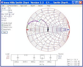 Which intuitively is better than a big black line but by how much? Click on the Return Loss button and you get:
 Which shows the return loss over the transmitting frequencies will be better than 20dB ie a good match
I can't wait to smoke test this!
73's
Richard
This is really easy and full credit to the author. Once we have our matching network at the design frequency we can select the option to "Sweep SC" on the right hand edge of the window and a black line shows how the load is transformed as the frequency is swept according the the span setting. I got the following:


I can't wait to smoke test this!
73's
Richard
Thursday, 15 December 2016
Unilab 10m FM conversion Transmitter PA mods - Driver Stage
I had a chance to rummage around in the junk box yesterday. If you're wondering why I would turn to a transistor I recover from a radio, instead of buying online, see my post at http://vk6tt.blogspot.com/2016/05/hf-transmitting-transistors-for-qrp.html
Anyway, the first radio touched was a Philips 828 E band. They contain a BLY87 which would be a good candidate as a driver. However, they are stud mounted so that could be awkward.
The next radio was a RT85 for low band. They use a Mitsubishi 2SC1971 as a driver which is a nominal 6W VHF high band transistor. Not quite the 10W I was looking for but it forced me to rethink my approach.
The MRF247 final transistor has a gain of 8.5db at 175MHz. Adjusting for frequency at 6dB per octave that equates to 23.8dB at 30MHz. Much more than the 10dB I was allowing for. The full gain at 30MHz cannot be used if oscillations are to be avoided. However, if I shoot for 13dB of gain then the 2SC1971 would only be required to produce 5W, well within it's rating.
Adjusting the quoted gain for frequency suggests the 2SC1971 has 25dB of gain at 30MHz. Again, way too high. But the prospect of avoiding a pre-driver stage is a tease since a gain of 13dB from the driver stage dictates an input power of 250mW to achieve 100W from the PA strip. The exciter delivers 100mW. Quite close and maybe the gain per stage I have allowed is too conservative.
I'm going to try just a driver stage and dispense with the pre-driver.

I had to revise the input stage to the PA transistor for the increased collector load the driver stage required. After several iterations with the smith chart I concluded the higher collector load required meant the existing matching configuration could not be made to work.
My approach now is:
73's
Richard
Anyway, the first radio touched was a Philips 828 E band. They contain a BLY87 which would be a good candidate as a driver. However, they are stud mounted so that could be awkward.
The next radio was a RT85 for low band. They use a Mitsubishi 2SC1971 as a driver which is a nominal 6W VHF high band transistor. Not quite the 10W I was looking for but it forced me to rethink my approach.
The MRF247 final transistor has a gain of 8.5db at 175MHz. Adjusting for frequency at 6dB per octave that equates to 23.8dB at 30MHz. Much more than the 10dB I was allowing for. The full gain at 30MHz cannot be used if oscillations are to be avoided. However, if I shoot for 13dB of gain then the 2SC1971 would only be required to produce 5W, well within it's rating.
Adjusting the quoted gain for frequency suggests the 2SC1971 has 25dB of gain at 30MHz. Again, way too high. But the prospect of avoiding a pre-driver stage is a tease since a gain of 13dB from the driver stage dictates an input power of 250mW to achieve 100W from the PA strip. The exciter delivers 100mW. Quite close and maybe the gain per stage I have allowed is too conservative.
I'm going to try just a driver stage and dispense with the pre-driver.
I had to revise the input stage to the PA transistor for the increased collector load the driver stage required. After several iterations with the smith chart I concluded the higher collector load required meant the existing matching configuration could not be made to work.
My approach now is:
- C1, currently 100pF, is padded with a 10nF capacitor,
- removed the 2 turn coil L1,
- pad the input of the strip-line with an extra 860pF of capacitance using two capacitors, 470pF and 390pF.
73's
Richard
Saturday, 10 December 2016
Unilab 10m FM conversion Transmitter PA mods - Final Stage
So, we now turn our attention to the final part of the modification. I suspect this will be the hardest part of the whole project. The existing PA needs a fair amount of work to get it running at 10m.
The challenges arises because:
If the MRF247 cannot be coaxed into service it will effectively mean a whole new PA strip. Perhaps Murphy is elsewhere today.
Since the MRF247 is specified as a 75W transistor I decided that would be the target output power. However, I'd design the matching for each stage for a 30% margin for the output power i.e. almost 100W. It may transpire that I have more gain than the 10dB per stage I am allowing for and since the MRF247 could be driven towards 100W I wasn't going to say no to the extra 25W if it eventuated. There is no data that I could find on the series equivalent impedances outside the specified range of 136MHz to 175MHz so I had to make some assumptions for the matching networks. I assumed the following:

In an attempt to understand how the Unilab designers got the MRF247 to work outside it's specified range I looked closely at the input networks. I knew the BGY32 was a 50ohm output device. And the MRF247 was likely to have a series input impedance of 0.57+j0.3 at 77MHz. To test this assumption I tried a few software packages until I found one that helped me understand this: Iowa Hills Smith Chart software.
I found this software intuitively easy to use. It wasn't the first Smith Chart software that I tried but like the filter software from Iowa Hills this is clearly written by someone who uses the software. I do recommend you try this software.
With the values shown on the circuit I was able to confirm a match was possible at 77MHz between 50ohmns and the PA transistors input impedance of 0.57+j0.3. This was true whether the stripline was modelled and an inductor or as a stripline. In the end I left is as an inductor:

The next step was to see what I would have to change to get this existing input matching section to match a source of 9.4ohms. This would be the collector load required for a driver to deliver almost 10W. For a class C amplifier this is derived from the formula Po = Vcc * Vcc / ( 2 * R ).
With just an extra capacitor and a different inductor we can achieve a good match. An additional 180p capacitor at the BGY32 end of the stripline and an inductor of 86nH replacing the coil that is there is all that might be required.
 So far, so good. I repeated the exercise for the output stage and decided that two 34.5nH coils and a 510pF capacitor to pad C603, or a 220p and 270p in parallel, would be a good starting point.

I'm going to make the changes outlined above and check my junk box for driver transistors before I progress any further.
73's
Richard
The challenges arises because:
- The BGY32 module is designed to work between 66MHz and 88MHz. This has to be replaced with a home brew alternative, and
- The MRF247 was never specified outside the 136-175MHz band, and
- I will try to use transistors that are readily available.
If the MRF247 cannot be coaxed into service it will effectively mean a whole new PA strip. Perhaps Murphy is elsewhere today.
Since the MRF247 is specified as a 75W transistor I decided that would be the target output power. However, I'd design the matching for each stage for a 30% margin for the output power i.e. almost 100W. It may transpire that I have more gain than the 10dB per stage I am allowing for and since the MRF247 could be driven towards 100W I wasn't going to say no to the extra 25W if it eventuated. There is no data that I could find on the series equivalent impedances outside the specified range of 136MHz to 175MHz so I had to make some assumptions for the matching networks. I assumed the following:
In an attempt to understand how the Unilab designers got the MRF247 to work outside it's specified range I looked closely at the input networks. I knew the BGY32 was a 50ohm output device. And the MRF247 was likely to have a series input impedance of 0.57+j0.3 at 77MHz. To test this assumption I tried a few software packages until I found one that helped me understand this: Iowa Hills Smith Chart software.
I found this software intuitively easy to use. It wasn't the first Smith Chart software that I tried but like the filter software from Iowa Hills this is clearly written by someone who uses the software. I do recommend you try this software.
With the values shown on the circuit I was able to confirm a match was possible at 77MHz between 50ohmns and the PA transistors input impedance of 0.57+j0.3. This was true whether the stripline was modelled and an inductor or as a stripline. In the end I left is as an inductor:

The next step was to see what I would have to change to get this existing input matching section to match a source of 9.4ohms. This would be the collector load required for a driver to deliver almost 10W. For a class C amplifier this is derived from the formula Po = Vcc * Vcc / ( 2 * R ).
With just an extra capacitor and a different inductor we can achieve a good match. An additional 180p capacitor at the BGY32 end of the stripline and an inductor of 86nH replacing the coil that is there is all that might be required.


I'm going to make the changes outlined above and check my junk box for driver transistors before I progress any further.
73's
Richard
Wednesday, 7 December 2016
Unliab 10M FM Conversion - Exciter Board
If you have been following along we pick up from the last instalment and detail what changes are needed once the transmit VCO board is working. The big issue with this project is the output spectrum. We have taken a 80MHz broadband design and pushed it down to 30MHz. As a result, the output spectrum resembles that of a tripler!
The problem stems from the amplifier stage immediately after the VCO board. This is the final stage in the exciter and it really works well as a tripler. And it is quite good as a doubler too! What I did was to alter the circuit back to a narrow band design with some selectivity.
I now have a 100mW exciter but I will have to consider the output spectrum more carefully as I progress to rebuild the PA.
73's
Richard
The problem stems from the amplifier stage immediately after the VCO board. This is the final stage in the exciter and it really works well as a tripler. And it is quite good as a doubler too! What I did was to alter the circuit back to a narrow band design with some selectivity.
- Pad C324, the 100pF input capacitor, with 1000pF
- Remove C328 and C329, the two 1000pF emitter bypass capacitors
- Remove L305, the tapped bifialar transformer wound on a ferrite bead.
- Remove the resistor that was in parallel with this. Mine was a 680ohm resistor.
- Clean out the holes and solder in 3 pins from a 0.1" header strip.
- Take a T50-2 toroid, wind 16turns with a tap at 4 turns. (I have plenty of these if you're stuck)
- Solder the toroid across the outside of the three pins. The cold end, that closest to the tap, goes to the pin towards the centre of the board.
- The tap goes to the middle of the three pins.
- Solder a trim cap, say 40pF, across the two outside pins of the header.
- Adjust FVR301 for maximum D voltage on TP303
- Tune the trim cap for strongest output on 10m.
I now have a 100mW exciter but I will have to consider the output spectrum more carefully as I progress to rebuild the PA.
73's
Richard
Sunday, 4 December 2016
Unilab 10m FM conversion - Transmitter VCO Board
The transmit VCO proved to be much more challenging. I started with calculated values for the capacitors and used the same biasing of the varactors as I discussed in the receiver VCO conversion.
This time I used a toroid in the tank circuit, a T50-2. I started with 12 turns but ended up removing 2 turns. I removed the resistor and thermistor and soldered a link on the source choke to ground. While I used a 91k resistor in the gate, 100k will be fine. The picture below still shows the varactor biasing diodes I put in place for testing. Remember to remove them before installation back in the radio!

Installing the VCO board back in the radio I found myself going in circles solving loop lock up followed by a poor output spectrum. Rather than bore you with the sorry tale let's cut to the chase!
The mmic buffer used is very susceptible to being over-driven and generating harmonics. Yet a small reduction in output means the pre-scaler does not get sufficient drive to work properly. I made the following changes:
If you haven't been able to find the circuit for this radio on the web here is a partial snapshot to help:

At this point I have a PLL which locks up and a nice waveform going into the remaining stages of the exciter.
Just like the receiver VCO board, I now looked at the variation in the control voltage as I locked at the top and bottom end of the 10m FM segment. The maths demonstrated that the existing loop filter was "awkward". I ended up putting a second varicap in parallel with the existing one and changing a few capacitor values. Since making the initial mods using a toroid I had found a suitable variable inductor and I substituted that for the toroid. It makes adjustment for lock that much easier. I settled on a 3.5V variation in the control voltage and ignored the loop filter. I might revisit the loop filter after everything else is working.
The final(?) VCO component values are shown on the following schematic:

The balance of exciter board mods are in the next instalment.
73's
Richard
This time I used a toroid in the tank circuit, a T50-2. I started with 12 turns but ended up removing 2 turns. I removed the resistor and thermistor and soldered a link on the source choke to ground. While I used a 91k resistor in the gate, 100k will be fine. The picture below still shows the varactor biasing diodes I put in place for testing. Remember to remove them before installation back in the radio!

Installing the VCO board back in the radio I found myself going in circles solving loop lock up followed by a poor output spectrum. Rather than bore you with the sorry tale let's cut to the chase!
The mmic buffer used is very susceptible to being over-driven and generating harmonics. Yet a small reduction in output means the pre-scaler does not get sufficient drive to work properly. I made the following changes:
- The 7p coupling capacitor is removed and I put a 2p5 and a 1p5 capacitor on the board, one on each side. This reduced the drive and the distortion on the output of the VCO board was much less apparent.
- I then bypassed R407 with a wire link to get the pre-scaler working correctly. And finally,
- I removed R411A to reduce the gain of this buffer and improve the output waveform still more.
If you haven't been able to find the circuit for this radio on the web here is a partial snapshot to help:
At this point I have a PLL which locks up and a nice waveform going into the remaining stages of the exciter.
Just like the receiver VCO board, I now looked at the variation in the control voltage as I locked at the top and bottom end of the 10m FM segment. The maths demonstrated that the existing loop filter was "awkward". I ended up putting a second varicap in parallel with the existing one and changing a few capacitor values. Since making the initial mods using a toroid I had found a suitable variable inductor and I substituted that for the toroid. It makes adjustment for lock that much easier. I settled on a 3.5V variation in the control voltage and ignored the loop filter. I might revisit the loop filter after everything else is working.
The final(?) VCO component values are shown on the following schematic:

The balance of exciter board mods are in the next instalment.
73's
Richard
Saturday, 3 December 2016
Unilab 10m FM conversion - Receiver VCO and PLL Stability
I noticed that while switching from receive to transmit and back again that sometimes the receiver PLL would drop out of lock. Here then is a brief discussion of how I resolved this issue.
The first thing I did was measure the VCO voltage at the minimum and maximum frequencies I had loaded in the eeprom. To achieve this I had to adjust the inductor and trim cap in the VCO until I had lock with a low control voltage. Otherwise, I couldn't get a lock at the high frequency. This immediately told me I had at least one issue to address.
Frequency Tuning Voltage
50.74 MHz 0.1V
51.29 MHz 6.7V
Clearly that leaves little margin for things like temperatures change given the maximum tuning voltage under lock is approximately 8V. The control voltage swing needs to be much less than this, but how much?
Looking at the loop filter values left me nonplussed. I'd never seen a loop filter like this before. I have highlighted the relevant components on the schematic below. I was tempted to re-design this part of the radio but went away and though about this for some time.It eventually dawned on me that there was an embedded lead lag filter, circled on the schematic below. Ignoring everything else I crunched some numbers which suggested that these values would be appropriate if the range in tuning voltage was more like 1V.

Looking at the component values used, below, the most expedient fix would be to change the 2p7 capacitor in series with the varicap.The first capacitor I tried was 15pF which gave a variation in the control voltage of 3.5V - 5.0V. Before I could measure that I had to get the PLL to lock again. I had seen this before with the transmit VCO. Despite the oscillator oscillating, the pre-scaler was giving an erroneous reading due to the input signal being too low. I added a 100 ohm resistor in parallel with R202 which fixed this.
At this point the receiver synthesiser mods are almost complete. After putting the lid on the receiver I noticed the loop went out of lock on one channel. The channel either side was fine. Remove the lid and the channel locked up. Given the control voltage on the test point did not shift significantly for the frequencies above and below this troublesome channel I ruled out the lid modifying the oscillator frequency.
I cut a piece of blank circuit board to the size of the VCO enclosure. As I placed it into the enclosure as a temporary shield and I expected the lock issue to arise. It didn't. But putting the lid on while the temporary shield was in place still unlocked the loop. So the issue wasn't with the VCO.Which ruled out so many weird causes that I was stumped as to what it could be.
After sliding various assortments of metal around the top of the receiver enclosure I confirmed the issue is arising within the section housing the eeprom. I still hadn't got to the bottom of this. The frequency, 50.760 MHz isn't a harmonic of the crystal oscillator or even the 750kHz reference going into the PLL chip. But you can set the frequency 10kHz either side of this with no issue.
However, after another go at solving this I discovered the problem was due to incident light, and not an RF issue at all. It turns out that this one channel in the eeprom changed value if it was in darkness. I couldn't replicate this in my eeprom programmer but it definitely was due to darkness changing the data on the output pins of the eeprom. Anyway, I burned another eeprom and problem solved.
I have put the lid on, tightened the screws and next time I will start writing up the transmitter conversion.
Regards
Richard
The first thing I did was measure the VCO voltage at the minimum and maximum frequencies I had loaded in the eeprom. To achieve this I had to adjust the inductor and trim cap in the VCO until I had lock with a low control voltage. Otherwise, I couldn't get a lock at the high frequency. This immediately told me I had at least one issue to address.
Frequency Tuning Voltage
50.74 MHz 0.1V
51.29 MHz 6.7V
Clearly that leaves little margin for things like temperatures change given the maximum tuning voltage under lock is approximately 8V. The control voltage swing needs to be much less than this, but how much?
Looking at the loop filter values left me nonplussed. I'd never seen a loop filter like this before. I have highlighted the relevant components on the schematic below. I was tempted to re-design this part of the radio but went away and though about this for some time.It eventually dawned on me that there was an embedded lead lag filter, circled on the schematic below. Ignoring everything else I crunched some numbers which suggested that these values would be appropriate if the range in tuning voltage was more like 1V.

Looking at the component values used, below, the most expedient fix would be to change the 2p7 capacitor in series with the varicap.The first capacitor I tried was 15pF which gave a variation in the control voltage of 3.5V - 5.0V. Before I could measure that I had to get the PLL to lock again. I had seen this before with the transmit VCO. Despite the oscillator oscillating, the pre-scaler was giving an erroneous reading due to the input signal being too low. I added a 100 ohm resistor in parallel with R202 which fixed this.
 |
| Receiver VCO values before change to 2p7 capacitor |
At this point the receiver synthesiser mods are almost complete. After putting the lid on the receiver I noticed the loop went out of lock on one channel. The channel either side was fine. Remove the lid and the channel locked up. Given the control voltage on the test point did not shift significantly for the frequencies above and below this troublesome channel I ruled out the lid modifying the oscillator frequency.
I cut a piece of blank circuit board to the size of the VCO enclosure. As I placed it into the enclosure as a temporary shield and I expected the lock issue to arise. It didn't. But putting the lid on while the temporary shield was in place still unlocked the loop. So the issue wasn't with the VCO.Which ruled out so many weird causes that I was stumped as to what it could be.
After sliding various assortments of metal around the top of the receiver enclosure I confirmed the issue is arising within the section housing the eeprom. I still hadn't got to the bottom of this. The frequency, 50.760 MHz isn't a harmonic of the crystal oscillator or even the 750kHz reference going into the PLL chip. But you can set the frequency 10kHz either side of this with no issue.
However, after another go at solving this I discovered the problem was due to incident light, and not an RF issue at all. It turns out that this one channel in the eeprom changed value if it was in darkness. I couldn't replicate this in my eeprom programmer but it definitely was due to darkness changing the data on the output pins of the eeprom. Anyway, I burned another eeprom and problem solved.
I have put the lid on, tightened the screws and next time I will start writing up the transmitter conversion.
Regards
Richard
Subscribe to:
Posts (Atom)