Pages

Tuesday 26 September 2023

Joule Smasher Led Flasher - Dud CR2032 cells

 I should have known better. Buying no-name batteries is a real mistake.

After the used CR2032 cell ceased working I changed it for a fresh cell from the packet below. 


Almost immediately I was suspicious.Test results show it was next to useless. It stopped somewhere between 9am yesterday and today. Say 34.5 days. I mean really? Even the rubbish AG3 cell lasted 19 days in the same test fixture. What a waste of money.


Meanwhile, the AA battery just keeps powering along on-track for 10 years of life.

Saturday 23 September 2023

2M Low Pass Filter from RG142

Having "failed" to build a suitable bandpass filter with RG142 I tried the low pass filter based on stubs concept from here. While it does little to improve reception where pager intermod's are a problem it will provide peace of mind when transmitting. RG142 is easy to work with since you don't have to worry about inner conductors gong soft while soldering and you can solder the shield without needing pigtails. RG58 or RG213 are much harder to work with.

With the nanoVNA construction is simple. I attached the three stubs (for RG142 I started with 180mm, 120mm and 90mm) and the inductor.

Looking at a graph of S21 versus frequency it is easy to see where the stubs are resonant.With the Australian band plan most of my FM transmitting will be around 146.5MHz. So with markers placed at 293MHz, 439.5MHz and 586MHz I carefully trimmed each stub so peak attenuation fell on each marker. Changing the frequency span to zoom in to these frequencies is helpful as those markers move toward the dip. By careful I mean as small a cut as you can manage as you get close. I always overshot on the higher harmonics.

My first attempt:


I didn't trim the stubs very well but it showed promise.


The final result:

After replacing the coax I had trimmed too much I once again tried to get it spot on. This time I got closer and the biggest challenge was getting (take your pick of terminology) the input return loss, S11, or VSWR down. 

Initially the input return loss was not as good as the initial version. This was due to the stubs, now trimmed to a different length, having a different capacitance at 2m. After experimenting with different inductors and looking at the Smith Chart of S11 I concluded I needed some capacitance on the output pin so the inductor could tune the input correctly. Once I discovered this it was plain sailing. I used a 1-10pF variable capacitor but I also had good results with a piece of copper foil spaced closely over the ground plane.It just wasn't as good mechanically so I switched to the variable capacitor.

Yes, you can tune for a ridiculously low return loss

With careful trimming but I still cut too much off the shortest stub


Conclusion

Easy to achieve a 40db reduction or more in the second and third harmonics with negligible loss on 2m. That harmonic rejection is not as good as the bandpass filter made from LDF4-50 unless you tune it with absolute precision. However, it has a loss of under 0.1dB while the LDF4-50 filter had 0.7dB of loss. Perhaps that is just bragging rights. Either filter will make a difference to harmonics levels.

It is straight forward but some test equipment helps. I could just have easily tuned this with a signal generator and a scanner with a S meter. But it does make me realise just how profound the step change in home brew has been with the nanoVNA.

I like that the stubs made of RG142 cannot be detuned by touching them except if you put your finger right on the open end.

It worked so well it is now permanently installed. I will give thought to housing it in a suitable metal enclosure to improve the installation. I own a couple of the Chinese "Harmonics in a box" handhelds. I never have had cause to use them but one day I might. When the day comes one of these filters is peace of mind.


Friday 22 September 2023

2M Bandpass Filter from LDF4-50


To recap, RG142 coax proved unsuitable due to an insertion loss for a narrow filter of around 3dB. RG213, which has a larger diameter, was encouraging with an insertion loss around 1.5dB. LDF4-50 is still larger in diameter. How did it go?


Circuit

The 
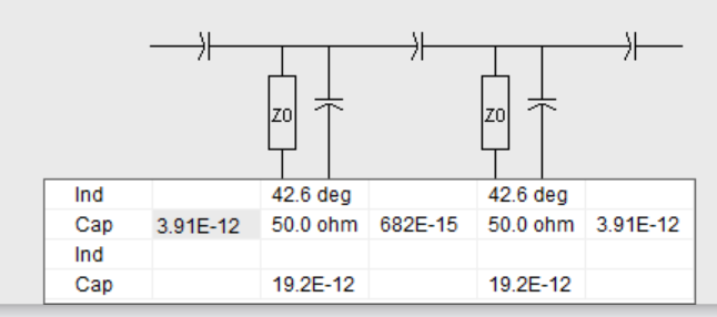
filter was very loosely based on the RG142 filter. With all the practice I had tuning up such filters I didn't stick to this religiously. My coax length was a guess, the construction technique more devil may care than finesse and everything was made up as I went along.

Substituting air space copper strips for the 0.7pF capacitor and lengths of RG142 for the coupling capacitors I was surprised when this tuned up and worked without any grief.

Murphy was absent.

I passed the two length of LDF4-50 through holes just wide enough to accommodate the cable. Then I wrapped several turns of copper wire around the copper sheath to stop the LDF from falling back out. A firm result that when soldered was surprisingly robust.

Some more re-purposed copper sheath to connect the tuning capacitors and a section of RG142 for terminating capacitors. The RG142 was a little hard to work with and if I used RG142 again I would have allowed spacing for 5cm of RG142 without such a sharp corner. 


 Initial Results

About 0.7dB loss on 2m, 1dB at the band edges and 7dB at 152MHz. Second harmonic was -40dB and the 3rd harmonic was -58dB. 


I haven't finessed this as it is already fit for purpose and proves the concept. No point twiddling those nice variable capacitors too much since that can wear out any gold flashing that exists on the threads.

Results in Practice

I once had a Motorola radio programmed for 2m which was so poor it appeared to be getting cross modulated by broadcast band FM signals when I had it in the car. Stupid varicap tuned printed inductor front ends! My suspicion is there was something wrong so I gave it away for parts.

However, I no longer have any radio which suffers from inter-modulation at the home QTH so I can't confirm if it truly helps. Should I go mobile again I will update you on my findings.

I found it could handle 40W without issue and had no apparent impact on weak signals.


Conclusion

LDF4-50 can be used to make outstanding 2m band pass filters. While cumbersome in size compared to filters made with wire wound inductors I can't make inductors with a Q of around 500 to achieve the same results. 

While 7dB of rejection for pagers doesn't sound much it should be noticeable in practice.

Sunday 17 September 2023

2M Bandpass Filter from RG213 Coax

So RG142 coax proved unsuitable. Perhaps RG213, which has a larger diameter, would work?

Initial results were encouraging. Loss was now about 1.5dB, a  1dB improvement just by switching to a wider coax.


Circuit

The filter was loosely based on the RG142 filter. With all the practice I had tuning up such filters I didn't stick to this religiously. My coax was a few cm longer and resonating capacitors adjusted to suit. I still need to revise the terminating capacitors since I have less capacitance than the original circuit  required.


 Initial Results

Prior to Changing 4.7pF Terminating Capacitors

I didn't persist with this because I spotted a length of LDF4-50A, a half inch coax which was wider in diameter than RG213, so I thought I would give that a go.

More on that later.