Pages

Saturday, 23 July 2022

10W Class AB amplifier - Modest Success

After letting the smoke out of yet more transistors I finally managed to get a repeatable 6W out of the amplifier. I made two changes to the amplifier:

  1. The output transformer was changed to a larger binocular core, and
  2. The input transformer was changed to a 9:1 transformer instead of a 4:1 transformer.

The first change appears to have resolved the issue where a few amps was reducing the return loss. See the post here for what was happening.

After popping yet another transistor I suspected the voltage across the base with the 4:1 transformer was exceeding the Vbe rating of the transistor with fatal results. With the new transformer I have yet to pop the transistor.

However, I still can't achieve a continuous 10W because the transistor, which I believe is rated for 17W,  starts shutting down as the junction temperature rises. I have a large finned heatsink so the cause of this is unknown at present. 

Note that I am measuring power using a single RF frequency, or carrier. Thus the 6W is equal to average power. This gives me hope that with a two tone test signal 12W PEP is possible.

Why the modest label? My goal was to achieve 10W PEP with a general purpose transistor. I had to use a RF transistor and at present I haven't measured 10W PEP though I believe the amplifier can achieve this with a two-tone test signal.

The best of the general purpose transistors available today that I tested was a 2SC6144 which achieved 4W with a single frequency on 80m. However, this was with the smaller output transformer so the full potential of this device has not been tested. If you try one please let me know what you achieved.

There are some obsolete transistors mentioned here that also delivered 4W continuous which shows the junk box can be a useful source.

73's

Richard


Monday, 18 July 2022

10W Class AB Amplifier - More ferrite needed?

 So I replaced the transistor and connected a 5.5Ω in series with a 100nF cap across the transformer. I then used the nanoVNA to look back to the collector from the output port. Varying the collector voltage from zero, and then 8.8v to 16v showed almost no shift in the return loss.

However, adjusting the bias for 2A of collector current really shifted the return loss curve.

Idle current - bottom curve    2Amps top curve

Given the collector voltage was largely unchanged, the transistor capacitance from the collector to base and emitter would have been relatively constant. So the only explanation left is the current changed the transformer's characteristics. 

Next step is to replace the transistor yet again (smoke escaped) and try a larger transformer.

73's

Richard

Wednesday, 13 July 2022

10W Class AB Amplifier - Further Development Results

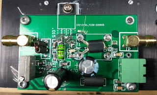
To test the conventional 9:1 transformer I blogged here I revised the board. The populated board is shown below:

With scars of many replacement transistors


I started with a 2SC1306, a once common CB output transistor. The smoke escaped all too quickly. I then tried a few general purpose transistors with unsatisfactory results.

One of the key things I noticed was that as the output was increased many transistors had a threshold. When that threshold was exceeded the output quickly dropped. If the bias was too high then thermal runaway also occurred.

The presence of this self-heating effect was noted in all of the transistors I tested, sometimes resulting in transistor failure. TO220 packages were better than TO126 packages presumably because they have a lower thermal resistance.

With only a few 2SC1306 left I switched to a 2SC2146. I was able to get close to 4W (40Vpp) but  eventually the smoke escaped.

I'm going to replace the transistor and see if a larger transformer is needed. 

73's

Richard


Tuesday, 5 July 2022

10W Class AB HF Amplifier - Initial Testing

I mentioned in this post that while the 2:1 transformers were successful, they still needed to be tested at higher power levels. This post covers that testing and some initial observations on transistors to be used in this amplifier stage.

10W(?) HF Test Amplifier using a CPU Heat Sink

Above is a picture of the amplifier using the two transformers I tested back to back in this post. At 4W continuous the transformer used in the output had no issues at 80m. I didn't get a chance to try other frequencies for an extended period because I was too busy letting out the smoke!

The initial transistor tested was a 2SC1096. From the datasheet we read:

·For audio frequency power amplifier and low speed switching applications
·Suitable for output stages of 3 to 5 watts car radio sets and car stereo

I expected this to work well at 80m and 40m given the Ft of 65MHz and it did so. Gain decreased with increasing frequency but across 160-15m I was able to achieve 4W continuous by adjusting the drive. 

2SC1096 Initial waveform at 1W output on 80m
 

The initial waveform at 1W output on 80m (above) suggested an increase in standing current would beneficial. I pushed the output up to around 40Vpp. 

2SC1096 4W Out

At this point I was not entirely happy with that downward sloping waveform after the positive peak of each cycle. But I pushed the bias too far and popped the transistor. However, my initial goal of testing the bias circuit and 50:12.5Ω transformers was achieved.

I replaced the transistor with a 2SC1226, which is broadly similar to the 2SC1096 i.e. it's not a RF transistor. Again I could get 4W easily.

2SC1226 at 4W Out

Of note is the initial downward sloping part of the waveform is around 0.06uS long, against the 0.08uS of the 2SC1096. Which sounds better though I suspect this is still not ideal.

The 50:12.5Ω transformer was replaced with a Ruthroff Type 9:1 on Small Binocular Ferrite. This gave me the potential to output more than 4W. I could still get 4W or so out but increasing the drive popped the transistor.

So progress has been good. I might have popped a couple of junk box non-RF transistors but I established the development board, biasing and transformers are all working.

Next time I will replace the transistor with an RF transistor so I have something to compare a number of readily available general purpose transistors against. 

73's

Richard


Sunday, 3 July 2022

9:1 Conventional RF Transformers 50:5.5Ω

I started with one of these binocular cores simply because it was already on the bench. It's also enjoyable to get something that has no data to work!

Using the braid from a piece of miniature coax cable as a 1 turn winding, I teased two holes in the closed end so I could wind 3 turns through the inside of the coax braid.

1 turn of braid, 3 turns inside braid

Good for 80m to 10m. What struck me some time later is the improved frequency response of this conventional style transformer compared to the 9:1 transmission line transformers I tested on the same core. This was contrary to my expectations that transmission line transformers had wider bandwidths. If I have learned anything in recent months it's that measurement beats folklore.

 I know that compensating caps are used in conventional transformers so I added 18, 22 and 27pF caps in turn across the 50Ω side.

Same transformer with different caps shunting 50Ω winding

The improvement in return loss is clear. I then repeated this on the 5.55Ω side of the transformer. The capacitors ranged from 220pF to 470pF. But these values appeared too large and I was getting inconclusive results. 

It appears a convectional transformer can be wound on these binocular cores. However, I need to do some reading on how to select the compensating capacitor values should they be needed. 

73's

Richard