Pages

Sunday 29 January 2023

Joule Smasher Led Flasher - Changes for Improved Life

I was building up another JSLF and before I finished populating the board I wanted to confirm how suitable the diode and moulded choke were.

With a 330R resistor tacked on the output for a 10mA load I  measured a current of 68mA for an efficiency of about 33%. This is well short of the roughly 80% suggested by the datasheet. The 330R was swapped to one giving a load of 4uA, the sleeping micro's consumption. The overall efficiency with the 4uA load was 30%.

When I apply the duty cycle of the current drawn I get a disappointing 33% result.

Swapping the schottky diode with some other general purpose shottky types showed no real change. I put some fast recovery type diodes on the list of things to order.

Turning my attention to the inductor I swapped in a 22mH power inductor. This gave an immediate improvement. Without boring you with the finer details the overall efficiency was now 74%. 

I was stunned that the moulded choke was so poor yet the life I was getting was amazing. I didn't have many of those 22mH power inductors and they were too large an inductance according to the application notes in the datasheet so I chose a physically large and plentiful in my parts bin 100uH as the new standard. 

Will the doubling in efficiency lead to twice the battery life?  It's too early to tell but after one day the battery voltage of the updated JSLF with a fresh AG3 battery is ~50mV higher than the previous 4 trials.

There is one more change to mention. 

Since the boost IC has an enable pin can it should be possible to get a few more percent in overall efficiency by only enabling the Boost IC when the LED and Micro are active. When the micro is asleep and the led is off the sleep current can easily be met by the capacitor on the 3.3V rail. This avoids the 30% efficient state for 99.5% of the overall flash cycle and should lift overall efficiency to around 80%.

So I now have a desk with 6 flashing LEDs nearby. In a week I should see the impact of these changes.

Update:

After 2 days I wasn't seeing the improvement I expected. I initially assumed it was battery characteristics but after the curves between trial 5 and 6 kept diverging I investigated and found that I was enabling the boost during the inefficient led off time period. 

With that fixed I expect to see curve (C) develop into a plateau and cross above curve (B) in due course.
Sunday 22 January 2023

Li Ion Battery Charging - Interim Results for Float Charging after 60 days

It has been over 60 days since I started this experiment. To recap the aim is to see if a CC/CV charge with a terminal voltage of a nominal 4.0V degrades cell capacity if the battery is left floating in the charger.  

To date I have not seen any consistent reduction in cell capacity.  At first glance two cells have got worse, two cells have improved. However, ambient temperatures have increased perhaps 10 degrees celsius as summer kicked in e.g. today is was 37C, the workshop interior was perhaps 43C. 

My suspicions is the swings in ambient temperatures are creating drift in the cheap battery tester being used. The reference voltage being used is the regulator output. A 78L05 has a drift of -1.1 mV/°C at 5ma of output but this assumes the junction temperature is unchanged. I would not be surprised if the drift in the supply rail was over 10mV.

This is compounded by the LM317 used in the constant voltage section of the charger drifting. As temperatures rise the output voltage falls. This might be a reduction in the order of 25mV for the change in ambient temperatures in the workshop. It is a bonus the voltage is not increasing given the high workshop ambient temperatures at present.

These temperature effects would explain the change in capacity of a few mAhrs. In another 60 days things will have cooled down again and I will post a more detailed update.

I should have been more rigorous in my testing and recording regime. My observations are not at known points in time so I cannot see a way to statistical test any change. Something I need to take on board when building an automated tester.

Thursday 19 January 2023

10W Class AB with parallel transistors - Qualified Success

I began some detailed measurements. In particular, I was interested at where the onset of distortion began. 

I started collecting data to build a chart on output power v input power. When I started measuring at higher output levels I found the buffer amplifier was in fact distorting above 1W of input power. Not surprising given it was designed to deliver 1W but something I hadn't considered till now.

But this means the first transistor I started measuring is probably not going to be the best transistor given the gain is lower than I wanted.


I call this a qualified success because I have a very robust and stable amplifier that delivers 10W, albeit distorted, and a maximum observed output of 14W with US$0.50 worth of transistors is outstanding.

At 5W it probably ticks all the boxes.

When time permits I'll test the second board I already have populated with a different transistor.

73's

Monday 16 January 2023

10W Class AB - Almost a Success, then the Smoke Escapes

I tried the first alternative transistor and saw mixed results. The distortion on peaks was still present. I slipped with the attenuator control and pushed the amp to 20W. Briefly. Then all the emitter resistors let go. 

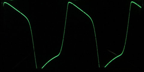
The distortion has me puzzled and is the same as the first amplifier with 10 parallel transistors. So I Googled and saw this waveform:
 
tube_drive_tone_control_maxed_out_480px 


The term "sharkfin" describes it well. The distortion in my amplifiers can be similar when pushed hard which does point to harmonics being present. The amount of distortion at 10W appears to depend on transistor type from results to date.
 

It appears I'm close to achieving 10W of output with 10 parallel SOT89 transistors. I'll replace the resistors and give it another try. A post with more detailed test results in due course.