Pages

Showing posts with label HF Transceivers. Show all posts

Saturday, 18 June 2022

4:1 Transfomers 50:12.5Ω - Success

I hadn't expected this to work out so easily. I already had a selection of bifilar wound transformers wound on these cores so it seemed like a good place to start. Terminated in 12.5Ω I looked at the 50Ω connection with the nanoVNA:

8t bifilar on a single core

Another single core with 12turns bifilar was tested and it was too many turns. Good for 160m to 40m though. 

Shifting to two cores side by side like a binocular core with 7 turns proved useful for all of the HF bands. Five turns could be a suitable starting point for 6m.

7t bifilar on two cores binocular style

To check the insertion loss I wired two of these transformers back to back. (50:12.5 + 12.5:50) 

The loss was negligible.

Loss across two transformers back to back


With 1W applied to this arrangement for 15 minutes the cores showed no sign of heating, perhaps 1degree above ambient.  

The goal was to find a suitable transformer for matching 50Ω to input of a 10W amplifier. If a 4:1 transformer is the solution then this has been achieved. But a 9:1 transformer may be required so another round of testing is needed.

73's

Richard


Thursday, 19 May 2022

80m Transceiver - Weaver Method of SSB : Preliminary

The building blocks are coming together. 

Analysis based on the inductors I had to hand suggested my receiver band pass filter may require changing. To facilitate that I decided to incorporate the three building blocks marked (a) onto one PCB. I will make the filters on a daughter board then fix that to the base board.

Rough layout and progress can be seen below.


73's

Richard

Friday, 18 March 2022

General Purpose Transistors in RF Amplifiers - Ouput Transistor Testing

After having my eyes opened by testing various buffer transistors I began substituting output transistors. Before testing currently available transistors I thought it useful to compare 6 alternatives in my junk box. These included fake 2SC2166 and 2SC1173 transistors, some genuine recovered CB finals, and a 30 year old BD139. All surprised me by appearing to work quite well. However, I wasn't driving them to get 1 Watt at this point.

Some of the testing results surprised me so I decided to give LTSpice a go to see if I could learn why I was surprised. That was a few days in my life I wont get back. However, using LTSpice made me accept that my spreadsheets may be in danger of becoming obsolete. The biggest challenge is being restricted to transistors for which a suitable model exists. But if you can find a spice model, LTSpice allows you to quickly rule out a device once everything is set up.

I have tested a number of devices now and I could not find a device that worked to my satisfaction. Issues noted were:

  • the output dropping as the temperature rose, sometimes by 20dB!,
  • distortion that required large increases in standing currents, and
  • a roll-off in gain that ruled out use beyond 7MHz

I found that driving 50 ohms from a 13.8V appears to be pushing the envelope. If I increased the supply voltage, or changed bias resistors to increase the standing current, I could get 1Watt out. This came at the expense of the transistor dissipating 3 watts.

Conclusion:

From my measurements the KSC3503 is worth trying. If you settle for less than 1 watt you will be happy. At 7MHz and below the TTC004B is also worth considering.

However, from results to date, a working output transistor recovered from the junk box is still better than trying to buy a general purpose transistor for RF output stage applications.

Next Steps:

Investigate if parallel transistors will meet the 1 Watt target. (Update - yes they did and very nicely. See posts tagged "Parallel" for details.)


73's

Richard


Friday, 4 March 2022

General Purpose Transistors in RF Amplifiers - Buffer Test Results

Please see the previous posts to understand I am trying to replace obsolete transistors in my standard Class A amplifier chain with something readily available today. Especially for the output stage.

Having settled on a driver transistor I thought that replacing the 2N2219 with a generic buffer transistor was going to be without issue. However, this assumption was wrong and the final stage testing has been delayed.

The 2N2219, used as the buffer, has a claimed transition frequency of at least 250MHz. I've spent the last 40 years playing with small signal NPN transistors and regularly noticed in the datasheets Ft of 300MHz or more. So I assumed that pretty much any transistor I dropped into the buffer stage was going to work.

It wasn't that simple. I started with something marked G1. This was ~1.2dB worse that the 2N2219. Hmmn. 

Grabbed something marked 1GM. This was ~1.5dB better than a 2N2219. Hang on. If this was a MMBTA05LT1, a Motorola NPN part marked 1GM, it should have been comparable with a claimed Ft of 330MHZ at 25mA.

An element of confusion was setting in. I decided to put the junk box recovered parts away and grab some nice new and fresh from packet NPN transistors. 

The first was something labelled a BC549 from a long forgotten Aliexpress vendor. I agree, this could still have been a junk box part. It was marked G1 and was better than the first "G1" I tried and the 2N2219 itself. Rolloff was improved by 1dB over the 2N2219.

After trying many such parts I tried a 2SC3356R, Ft of 7GHz. The rolloff at 20MHZ was now 2dB better than the 2N2219 version. A similar outcome was achieved when I recycled something marked R22 from a Philips FM900 VCO board. Some claim this marking is a 2SC3356. I'm not sure this was a 2SC3356 however it was a high Ft device.

Clearly, the higher the Ft the better. Which I hadn't expected given the feedback networks being used.

I crunched up a spreadsheet with a Hybrid Pi model of a Class A amplifier without collector base feedback to see what difference Ft made. With all assumptions unchanged, shifting Ft from 100Mhz to 330MHz results in a lot more gain at 20MHz. Collector base feedback reduces this gain, but the numbers supported selecting a buffer transistor with a higher Ft.

Later I fired up RFSim99 and loaded up the S parameters for a Renasas 2SC3356. Fiddling with the emitter and feedback resistors suggested a minor variation in values would be better to improve the match to 50 ohms. I will use those values going forward. 

There are many 2SC3356 transistors on LCSC.  Since Renasas has discontinued this part I figured it would be prudent to include some in my next order so I opted for this 2SC3356 since it had curves that resembled those in the Renasas datasheet.


Conclusion:

Recycle, or spend a few extra cents if you're buying a transistor, and get something for the buffer with an Ft greater than 1GHz. This may be counter to the conventional wisdom that HF circuits do not need such a high Ft. But the difference could be as much as 3dB per stage. So for low level amplifiers with feedback to prevent oscillation I argue it makes sense since it could save an entire stage.

Now I can test a few final transistors.

73's

Richard


Sunday, 27 February 2022

General Purpose Transistors in RF Amplifiers - Driver Test Results

Having reworded the amplifier chain to use 2:1 transformers instead of 22uH collector chokes I have commenced testing. My approach was:

  1. Build the amplifier with transistors that were known to work and measure
  2. Transfer the output and buffer transistors to a know board and start substituting SOT-89 packaged driver transistors
  3. With a chosen driver transistors transfer everything to another new board and after confirming a SOT23 buffer would work start substituting final transistors.

Being a known good design the amplifier worked with the original transistors. I adjusted the output for 10v pp at 1MHz. The roll-off at 20MHz was 2.9dB. Looking at the inter-stage levels I concluded that most of the roll-off was split equally between the buffer and the driver. The output stage was almost flat (-0.2dB). 

After testing 10 different SOT89 driver transistors I found the average of the roll-off at 20MHz for the entire amplifier was now -3.7dB, a deterioration of 0.8dB. I explain that by the difference in Ft: the original driver, a 2N4427, has a transition frequency of at least 500MHz, compared with the transistors tested having a typical transition frequency of 100MHz. 

While I only tested one device from each packet, the best transistor was the BCX56 which was just 0.4dB worse than the 2N4427. I'm comfortable using that transistor because it also appears to have the highest Ft at the collector current being used (~180MHz at 42mA from the datasheet chart).

The worst transistor had a claimed 210MHz typical Ft at 500mA. But clearly the Hottech 2SC4672 does not perform very well at a 42mA collector current. That's probably why there is no chart! 

And be wary of just buying any BCX56. I checked a few datasheets and in this application I would only use a BCX56 where there was a chart of Ft versus current, or a stated Ft in the vicinity of 50mA. Of course, it you buy from Aliexpress then you have entered a lottery.

Conclusion:

In a class A amplifier around 30mW output you can use a 10cent transistor at HF. This BCX56 is now my standard and should work very well in my 80m Weaver transceiver being developed. This removes the need for a 2N4427 for low-mid HF applications.

Now to test some higher power alternatives.

73's

Richard


Friday, 10 February 2017

Quadrature Networks for Phasing Transceivers - Measurement Matters

I previously blogged, here, how I used a Wheatstone Bridge to match resistors and was surprised by how easy it turned out to be. The reason for matching resistors was to build a quadrature network for audio phase shifting. You need sets of matched resistors to ensure the op amp gain of each stage is unity.

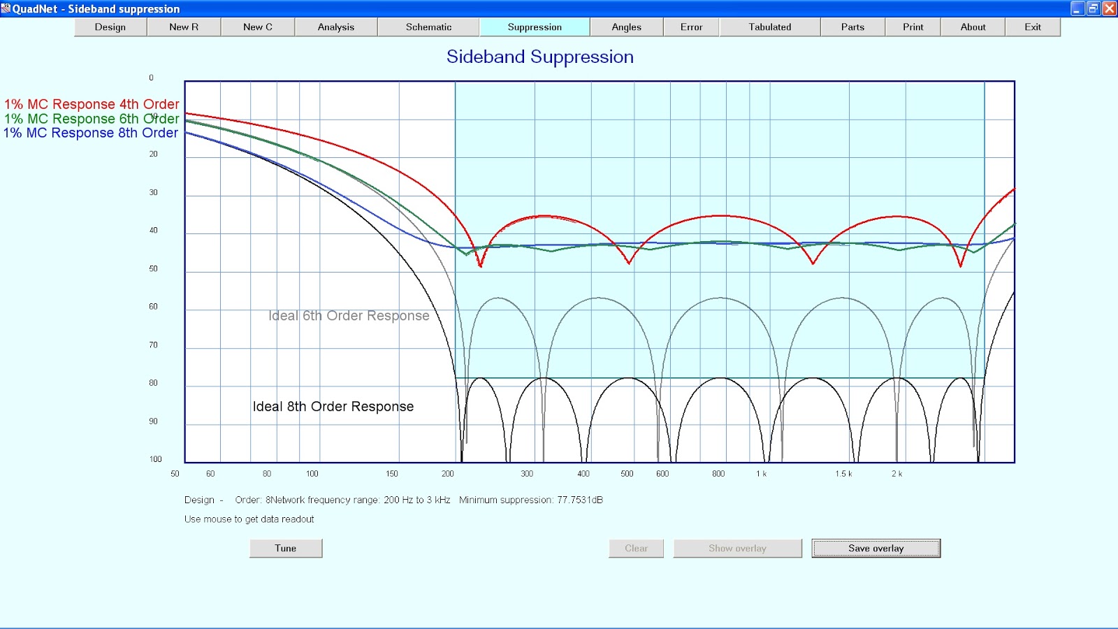
Today I was contemplating how complex does this network need to be. I fired up  Quadnet, from Tonne Software, and examined this issue. It turns out that if you are just going to accept that the best tolerance you can achieve is 1% then there is little point in using an 8th order filter. The monte carlo shows that the worst result for the 6th and 8th order filters is largely identical.


While 43db or so of sideband suoppression is a good starting point if you have the worst case outcome, the improvement with tighter tolerances is considerable. You might get closer to 55db of sideband suppression with a 6th order filter, or 77db with an 8th order filter.

I like the way this software allows you to measure a capacitor and then use that value to determine the required resistor values. With a bunch of measured capacitors you could tweak the placement of these and the resulting resistor values to get the best result.

More thought is needed before I decide on a course of action. However, it does illustrate the point that garbage in garbage out applies. Since I strive to get the best out of anything I do I will have to think about calibrating my digital LC meter now.

Regards
Richard VK6TT