Pages

Showing posts with label Tips. Show all posts

Thursday, 17 August 2023

Reflow Soldering with Ferrex Mini Gas Soldering Iron

The more I use this tool the happier I am with my purchase. Here is an example of reflow soldering a STM8S part which will naturally be running STM8eForth

Before soldering I bump some solder on the pads, shown below. Note pins 2 and 7 have an "Ear" of solder which I removed with my soldering iron tip before placing the IC.


With a small amount of flux smeared over the pads I place the IC and then use the Ferrex tool as a hot air pencil to reflow the solder. Result before removing flux below:

The part has reflowed nicely and just needs the flux cleaned off. Something to do when I finish the rest of the board.

Even though the proper hot air gun is within easy reach I often reach for the Ferrex tool. It is cordless, has in practice no air flow to blow parts around and is easy to wield. But the results are the same.


Sunday, 30 July 2023

Aldi Ferrex Gas Soldering Iron - Good for Hot Air Soldering

I went and brought a second one of these today. Much better value than my Iroda Gas Soldering Iron from Altronics. It lights easier, gets hotter and  works out about half the price. 

I use it as a cordless hot air gun and it's very good. As a soldering iron I can't say but given the heat this puts out it's probably good for that too.

Ferrex Mini Soldering Torch Kit

Friday, 28 July 2023

Flux "Testing" and Soldering Methods

Recently I watched in amazement a YouTube video of someone testing a large collection of soldering fluxes. I applaud the poster for testing the evangelical claims for certain brands of flux, but please use a technique that is meaningful. 

The first failure is trying to drag solder with what is clearly stale solder on the tip. See how the outside of the iron has slag on it? It wasn't cleaned before the test. And the hollowed tip exacerbates the problem because it holds a pool of stale solder. The exact opposite of what you want and the only tips I have like that are in my workshop bin. No wonder the resulting solder joints were so poor. 

The technique is also dubious. I never put a pool of solder on the tip to drag solder because the flux burns off. As an example of how far you can take this fresh solder approach you can, after tacking the part down, hold your fine solder wire so that it lies alongside the row of pins and pads. Then push the tip of the iron along the row of pins which melts the solder at the same time as the tip wipes across the pins. The result is fresh flux already in the solder doing it's job.

But yes, flux makes it easier and neater when drag soldering. Just not the way this was done. Stop and consider how much flux you need. Solder already contains flux, say 3%. Slapping on a teaspoon of flux is just ludicrous. My normal technique when drag soldering is to use a small paintbrush, trimmed to make it stiffer, and flux sitting in a suitable container. See below where the flux at the bottom of the container came from one of those cheap Chinese flux syringes. I am also trying a eyelash brush normally used for makeup because these are really cheap in a pack of 50. But even the most careful application of flux will still be more flux than is needed when drag soldering.


Sometimes I use a modified technique with a thicker solder wire. Stick the wire up into the flux and then as you push the tip along the pins pull the solder wire along the row of pins in front of the pool of solder forming on the tip. It takes a bit of practice but it avoids having to apply flux to the board first.

Any flux I have used was intended for electronics use and worked fine. Even rosin dissolved in metho works but I don't like how everything feels tacky afterwards because I'm clumsy. If you're slapping on gallons of flux like the video shows then yes you will find at times the fumes troublesome. But get your technique right and fumes become much less of an issue, if at all.

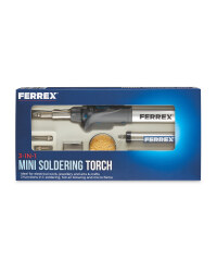
Ok, lets move on to soldering some surface mount parts. I was testing an Aldi butane soldering iron as a hot air gun and it worked well. I have three different butane hot air guns now and they have the advantage over the soldering station hot air gun in that there is no air flow. Something to keep in mid if your surface mount parts are blowing off the board at the slowest air setting!

I use a reflow technique based on wire solder and flux, not solder paste.

Step 1 - melt some solder onto the pads


Step 2 - brush some flux on


Step 3 - position parts - close enough!


Step 4 - Apply heat. I usually sit the board on my hot plate and use my soldering station hot air gun. But today it was just the butane powered hot air "pencil". The large inductors were too difficult so I ended up doing those with a soldering iron afterwards. on the hot plate they would have been easy to solder.

Step 5 - Touch up. I was rushing this because the whole purpose was to test the hot air pencil I brought so I didn't take as much care as usual. Not enough solder on a couple of joints but easily fixed with the iron.

Before Touch-up.

So nothing very challenging with this board but the hot air Aldi special worked very well. I'll buy another one this weekend. It works better than my Iroda butane powered soldering iron in this application and it doesn't blow parts around.


I repeated this with a USB charging connector which are difficult to solder with an iron though it can be done. Missed the ground pad on the connector but I show this because you can see what happens with too little solder. No pre-tinning of connector and be careful if you try to clean the pins (I don't) - once they bend you create problems getting them flat on the pads when soldering.


Let's do it again with more solder on the pads this time:


Final result after a quick clean with metho and cotton wool ear bud.

So there you have it - flux is your friend but you need far less than the you tubers use. And be critical when watching video's because all you're watching is opinion and ego. It's rarely the right way to do things. As someone who has used a soldering iron for over 50 years now I hope these couple of idea's get you thinking.


Footnote:

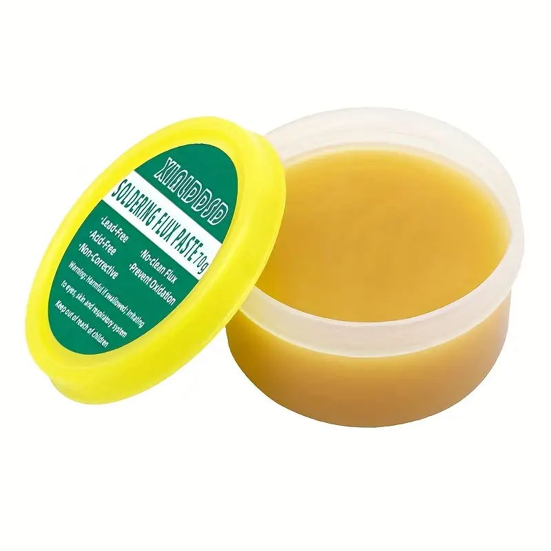
If you're buying flux I found that Temu is a good source. It's cheaper than other online sources though a bit annoying at times. Something like the following is what I use since I don't need another container to squirt the flux from a syringe into.

And if you do click the picture I might get some sort of referral bonus. While I have my doubts I'll get anything, if I do then I will stop the ads on this blog.

1pc soldering paste mild rosin environmental soldering paste flux pcb ic parts welding soldering gel tool for arrow metalworking 1

Saturday, 8 July 2023

How Good are Chip Resistors as Low Power 50 Ohm Terminations?

I purchased some 49.9 Ohm 1206 resistors to use as low cost, low power terminations or dummy loads in experiments. It turns out that when I measured them with the nanoVNA they were very good up to 150MHz and usable to at least 70cm. If it was non-critical then I'd use them at 23cm also.


Two samples of 49R9 1206 Chip Resistors


Friday, 24 February 2023

PCB - Surface Treatments


I was interested to see how important surface treatment was when PCB's are exposed to the elements.

My approach is take a LED flasher circuit board which can be left undisturbed for months, apply a treatment, and leave it exposed to the elements. 

Initial exposure to the elements was mid-day on 22/11/2022. That night a fierce electrical storm hit and gave everything a good drenching. Several such weather events took place over the test period.

    Date            Status

    22/11/22    5 Boards with different treatment and one board without treatment.
                       Placed outside in the open, surface mount component side facing upwards. 

    20/12/22    All 6 boards still functioning 

    23/2/23       Results after 3 months of harsh summer weather and several very wet rainfall events
                       as follows:


The test fixture after 3 months.

Conclusion:

Not a definitive test by any means. However, it appears any kind of treatment you have to hand is going to be better than no treatment when a PCB is exposed to the elements.

For low cost battery operated sensors housed in any kind of container I'd probably not bother. The life of such devices is several years at best, not decades, and by the time the battery needs replacing I suspect the device will be technologically obsolete.

Do you have any experience you'd like to share? I look forward to hearing your comments below.

73's

Thursday, 26 May 2022

Using 1210 Resistors as Thermal Bridges in 1W Transmitter

I mentioned in this post the concept of using surface mount resistors as thermal bridges. I've had a chance to explore this now and after various tests I'm completely satisfied this is a suitable way to heat-sink SOT-89 surface mount transistors in 1W HF amplifiers.

Balancing cost versus ease of installation  I settled on 4 pieces of 1MΩ 1210 resistors for each transistor. A 1MΩ resistor needs no further modification to isolate the collector voltage from ground. On an extended test the two parallel transistors had a  case temperature of around 130 degrees while dissipating a total of 3.4W and delivering 1W of RF to the dummy load.


I hope you find this tip useful.

73's

Richard

ps Please excuse the soldering. I'm using up some solder I would not recommend and and it's difficult to get a good joint without using too much.  That's compounded by it being too thick. 

My preferred solder is presently this one

My preferred flux is presently this one which I apply with a nylon type small paintbrush trimmed short to make the bristles a bit stiffer.

Monday, 21 February 2022

Surface Mount Soldering - Light- Box

This morning I was struggling with soldering a TQFP64 package. As I was inspecting for soldering defects I by chance discovered something something many will know - shining a bright light from the reverse side of the PCB can be very helpful.

I quickly rested the board on a frame over the bright light and attempted some touch up work. Wow! So much easier to see if those pesky solder bridges were being wicked away or otherwise being corrected. Later in the day I went to the shop with my better half, planning to swing by the hardware shop for some timber to make something more suitable. Left to my own devices I wandered around and stumbled on a bamboo organiser type box for around $10. Dimensions 12.5cm (H) x 17.8cm (W) x 31cm (D)


Flipped upside down with a hole and homemade LED light source mounted below the hole I now had a light-box for SMD soldering. 

No light


Light On

With the light on I can easily find solder bridges, whiskers and remnant flux. I can apply solder wick, or iron plus flux, to a bridge and easily see if it has corrected the problem.

Well worth the effort to make and it will be a huge timesaver for years.

73's

Richard

Tuesday, 2 November 2021

Noise in "Jelly Bean" regulators - conclusion

Some rules of thumb emerged from my investigations:

  1. If the data sheet makes no mention of a regulators output voltage noise then it's going to be horrible until confirmed otherwise. Maybe only good for digital projects.

  2. Any 78Lxx or LM317 type regulator followed by a  capacitance multiplier will deliver a clean supply voltage for low power analogue circuits. But the voltage drop of the capacitance multiplier needs to be either adjusted out or allowed for.

  3. A TL431 is a worthy alternative, and with a capacitance multiplier will deliver a cleaner supply voltage for demanding applications. 

My new standard for low noise regulation is the TL431 and capacitance multiplier. 

73's

Richard


Thursday, 29 April 2021

1284MHz PLL for 6cm Receive Converter

 I was recently fortunate enough to be given a Mitec Down Converter by VK6UM. 6cm but with a 140MHz IF. 

No problem, or so I thought, let's replace the 1280MHz oscillator with a PLL design generating 1284MHz. That would give a 144MHz IF.

I took a 23cm beacon  board previously described and hacked it around. 

First issue I faced was the PLL lock detection. I used the same MB1507 PLL chip but I increased the reference frequency to 500kHz. I had a few Forth commands that I could use over the serial link to change the frequency. While the VCO tuning voltage would shift according to the frequency I set, the lock detector never went into a lock waveform. After a few days I tried a 250kHz reference and straight away we had lock. 

Some qualitative testing of the PLL output was needed. After a bit of head scratching it occurred to me I could take a 800MHz output from my GSM test set, mix it with the 1284MHz signal, and look at the 484MHz result on the GSM's spectrum analyser. That worked and revealed some 250kHz spurs. I was able to reduce those with another rework of the loop filter values.

The next issue I faced was microphonics. Replacing the loop filter capacitors with tantalums as necessary reduced the level of microphonics when I tapped away with a screwdriver. Listening with an ICQ7a on narrow band FM to the 1284MHz signal was like a road crew sound check. Tap tap TAP TAP.... Useful test but I later realised I had forgotten to replace a 10uF MLCC on the regulator output feeding the VCO. By then it was all boxed up and installed. 

So the microphonics are there for now. I modified the PLL board based on what I had learned and in due course will rebuild the 1284MHz PLL. Hopefully when Larry, VK6UM, checks out the result it will be serviceable.

73's

Wednesday, 20 January 2021

Dishal Filter Alignment with the NanoVNA


When aligning bandpass filters it only takes me a few minutes of twiddling before frustration sets in. I had previously used the method attributed to Dishal as set out in Solid State Design. It is a very effective method although there is some set up needed. 

Over the years I had seen some very vague, if not useless, explanations of how to do this with a VNA. So I set out to discover for myself how this was done.  I threw together a 2 section narrow band pass made with coaxial stubs, tuned with high quality beehive capacitors. In the process I learned not only how to tune these filters but also how to design them with coaxial stubs.


Here then is how I use the NanoVNA to align multistage filters. (apologies to keen eyed readers who might noticed the dates/times of these images are mixed up. I lost a few so I had to mix two filter tuning records I had)

  1. I used OneofEleven's PC software to drive the nanoVNA but this guide should be near universal.
  2. OSL calibration as required
  3. Connect the filter to be aligned to the VNA. I'm going to use Channel 0 as the Input, Channel 1 as the output in this guide. 
  4. Use a suitable frequency span and add a marker for the desired center frequency eg 146.5MHz
  5.  Select a polar view of S11 and place a short to ground at Point A


  6. Adjust the marker using the "e-delay (ns)" field so it lies on the X axis. This is for convenience, the Y axis would also work. 


    7. Move the short to Point B

     
    8. Adjust the tuning capacitor on the first resonator until the marker rotates to be on the X axis but opposite to the rotated starting point.

    9. Move the Short to point C and tune the second resonator

    Remove the short. That's it. The picture in point 9 makes an important point. The whole trace is now on one side of the plot. That's irrelevant. What is important is the marker is on the right hand side of the two points which intersect the X axis. It started on the left hand side in point 8. Just try this, it is easy once you have had a go. Your traces will look very different to mine but the procedure is the same.

    So how did it work? As expected:

    I then decided to rebuild this for a narrower bandwidth. My tuning caps were just a tad too small so I used a center frequency of 150Mhz. You will notice below the peak is at 149.5Mhz. That's because I used a piece of floating PCB onto which the coupling capacitors were soldered. It was getting mechanically depressed during tuning changing the stray capacitance around the filter. 

     
    73's