Pages

Friday, 10 February 2017

Quadrature Networks for Phasing Transceivers - Measurement Matters

I previously blogged, here, how I used a Wheatstone Bridge to match resistors and was surprised by how easy it turned out to be. The reason for matching resistors was to build a quadrature network for audio phase shifting. You need sets of matched resistors to ensure the op amp gain of each stage is unity.

Today I was contemplating how complex does this network need to be. I fired up  Quadnet, from Tonne Software, and examined this issue. It turns out that if you are just going to accept that the best tolerance you can achieve is 1% then there is little point in using an 8th order filter. The monte carlo shows that the worst result for the 6th and 8th order filters is largely identical.
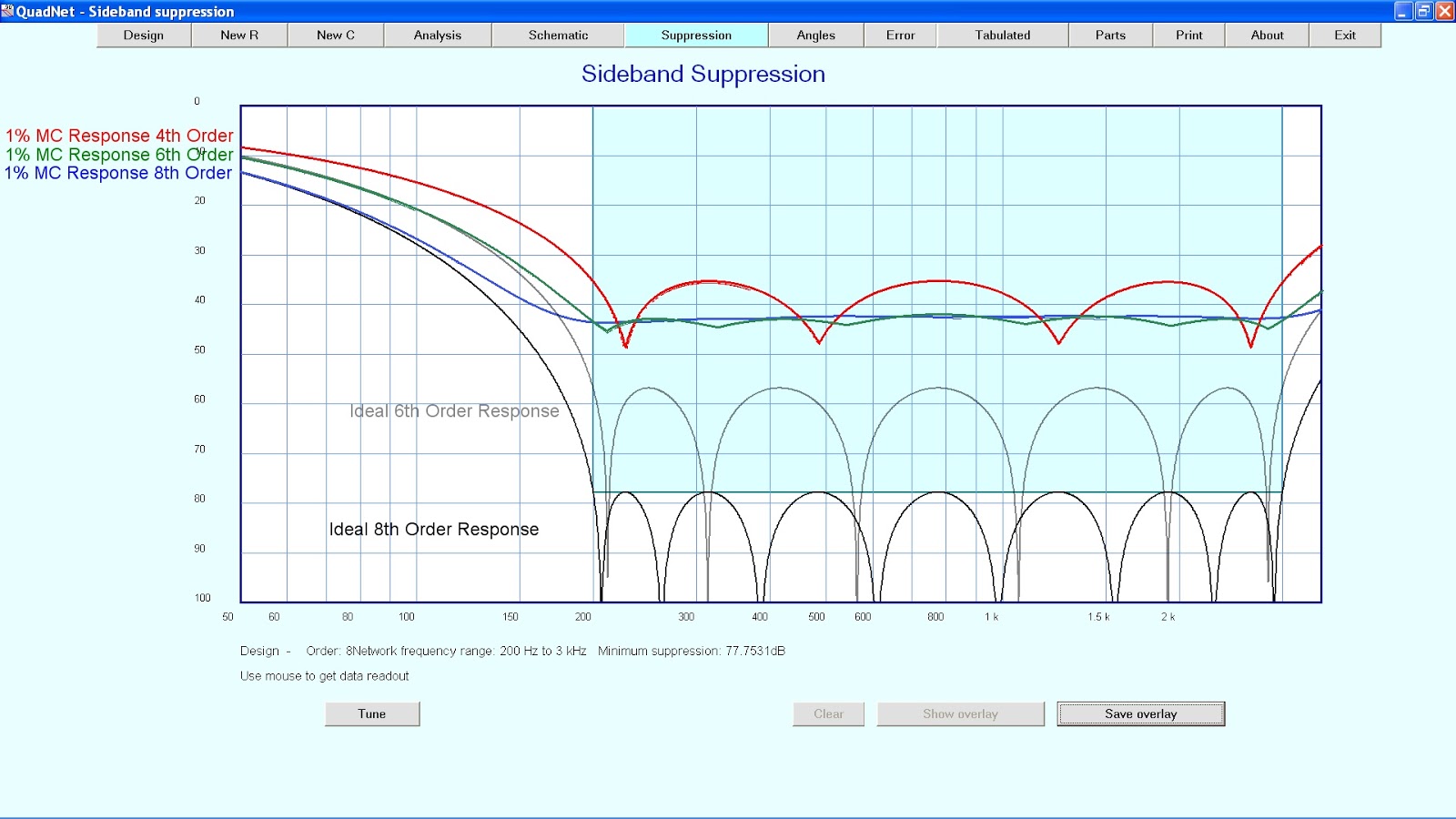

While 43db or so of sideband suoppression is a good starting point if you have the worst case outcome, the improvement with tighter tolerances is considerable. You might get closer to 55db of sideband suppression with a 6th order filter, or 77db with an 8th order filter.

I like the way this software allows you to measure a capacitor and then use that value to determine the required resistor values. With a bunch of measured capacitors you could tweak the placement of these and the resulting resistor values to get the best result.

More thought is needed before I decide on a course of action. However, it does illustrate the point that garbage in garbage out applies. Since I strive to get the best out of anything I do I will have to think about calibrating my digital LC meter now.

Regards
Richard VK6TT

Monday, 6 February 2017

AD8307 Power Meter - Mk2

I previously discussed the Mk1 version of this AD8307 power meter which had a x10 enhancement. One day the meter movement got damaged when I was trying to re-glue the scale. That was when I rebuilt it into the case you see above. I took the opportunity to avoid drilling a hole for the pot and to streamline the whole setting up process in use by revisiting how the reference voltage for the differential amplifier is generated.

I was never happy with the meter being driven off-scale until the pot had been adjusted. This time, I used a small micro to generate the reference voltage with a D2A based on a R2R ladder network. I wrote some code so that at power up, a form of reset, the micro started increasing the reference voltage until a threshold was reached. Then it simply stopped. Now I had automated this part of the process my Q measurement procedure became:
  1. find the peak response, 
  2. flick over to meter to the x10 setting, 
  3. turn the power off and back on, thereby resetting the micro and generating a useful reference voltage
  4. then to check the Q I look for a response 30dB less than the peak shown on the meter.

This made it even easier to measure -3db frequencies when looking at inductor Q, crystal parameters or trying to get that last 0.1dB improvement when adjusting filters.

Since the R2R network is only 4 bits, the reference voltage to the differential amplifier has 16 steps and I chose the upper resistor on the network to compress those 16 steps into the range needed.


Naturally you're welcome to the code and board design. Get in touch and I will shoot it across. I still haven't worked out how to make it available from my blog.

Regards
Richard VK6TT

Thursday, 2 February 2017

AD8307 Power Meter

Here is what my current AD8307 power meter looks like. I built this into a "box within a box" to enhance shielding. Inside the case is the battery, a lipo cell, and it's charging regulator. When I want to charge it I plug it into a 12V power supply. The remaining RF circuitry is built into a shielded compartment at the rear of the front panel bnc. It's basically 99% air inside the case!


I use a pretty much standard circuit for the AD8307. I think it was Wes Hayward, W7ZOI
and Bob Larkin, K7PUA that first promulgated this in QST, June 2001. I dispensed with offset and calibration adjustments since I was quite happy with AD8307 as it stands.

However, it occurred to me one day that being able to zoom into the response would be really handy when looking for the 3dB down point when trying to measure inductor Q with my fixture, here. While it would be easy to add a dc amplifier, the input signal would have to be adjusted so that the amplifier did not saturate. My modification was to add a differential amplifier based on an op amp so that rather than adjusting the RF levels, one could twist the pot until the reference voltage to the differential amplifier allowed for the amplifier to avoid being saturated.

The circuit for the first iteration of this is shown below.


My method for sweeping inductors in my test fixture was:
  1. find the peak response, 
  2. flick over to meter to the differential amplifier output, 
  3. adjust the pot to bring the meter to approximately 0dBm, and 
  4. then to check the Q I look for a -30dB response on the meter.
This was much less guess work on my part as to where the 3dB down frequencies were. And if you were trying to peak something it was much easier to see the peak.

I made some further improvements and will blog those soon.

Regards
Richard VK6TT